This thread has been locked.

If you have a related question, please click the "Ask a related question" button in the top right corner. The newly created question will be automatically linked to this question.

AMC1210: Problem with conversion (analog to digital)

Part Number: AMC1210

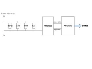
I want to measure the current in a shunt resistance (a shunt resistance that we connect in series to a device to measure its current consumption). I can choose the value of the shunt resistance among 4 resistances that are in parallel. 

The goal is to measure the current of 4 devices at the same time with the 4 module filters in the AMC1210. But first, I want to measure the current in one device with the 3rd module filter.

I use a NUCLEO-L446RG to communicate with the AMC1210 by SPI bus. And, in front of the AMC1210, I use an AMC1305 (delta-sigma modulator) to convert the analog voltage at the shunt terminals into a digital voltage.

I use the third order sinc filter of the 3rd module filter. I diseabled the Comparator filter, the Time unit and the Integrator unit. 

I use the pin ACK with an interrupt to get the digital data back from the filter.

Configuration : 

Control Register = 0x0B00

Clock Divider Register = 0x0000

For 3rd module filter :

Control Parameter Register = 0x0000

Sinc Filter Parameter Register = 0x0F1F

Integrator Parameter Register = 0x0000

Comparator Parameter Register = 0x0000

For the other module filters : default values

My problem is the digital data that the filter sends to the STM32 from its Data Register, it does not correspond to the analog voltage that I measure at the input of the AMC1305.

It seems like the conversion of the analog voltage into a digital voltage is not made correctly. 

And if I add some lines of code in my program the digital data is a bit different. The digital data value is different according to the time the program takes to get it back.

Maybe there is something that I didn’t understand about the filter and the timings.

Shunt 1 

Current (A)

0,5

1

1,5

2

2,5

3

3,5

4

(0,01Ω)

Input voltage AMC1305 (mV)

2,6

9,1

15,6

22,2

28,7

35,2

41,8

48,3

Vdevice = 5V

Data value theoretical (signed 16bits)

1699

5948

10196

14510

18758

23007

27320

31569

Output data value AMC1210 (signed 16bits)

3536

6796

10352

13702

17276

20576

23882

27832

Difference

1837

848

156

-808

-1482

-2431

-3438

-3737

Shunt 2 

Current (A)

0,05

0,1

0,2

0,3

0,4

0,5

(0,1Ω)

Input voltage AMC1305 (mV)

1,5

6,6

16,9

27,2

37,6

47,9

Vdevice = 5V

Data value theoretical (signed 16bits)

980

4314

11046

17778

24575

31307

Output data value AMC1210 (signed 16bits)

2846

5595

10853

16279

21679

27125

Difference

1866

1281

-193

-1499

-2896

-4182

Shunt 3 

Current (A)

0,01

0,03

0,05

0,07

0,09

0,1

(0,5Ω)

Input voltage AMC1305 (mV)

2,4

12,5

22,5

32,6

42,6

47,7

Vdevice = 5V

Data value theoretical (signed 16bits)

1569

8170

14706

21307

27843

31176

Output data value AMC1210 (signed 16bits)

2709

8137

13408

18481

23959

26650

Difference

1140

-33

-1298

-2826

-3884

-4526

  • Hi Annaelle,

    Our primary support for this device is out today - but I will do my best to help in the meantime. 

    One other question is how are you converting the output code from the AMC1210 back to volts in the STM? 

    Are you applying DC current through the shunts or AC? I would recommend using DC for the time being while we debug. 

  • Hi Alexander, 

    Thanks for the answer.

    - What do you mean when you say “the support for this device is out today” ? The support is out today the 8th April or the support is out today and forever ?

    - For the conversion, here is my understanding : I chose the third order sinc filter and I configured the OSR at 32. So the digital data can get a value from -32758 to +32768 that corresponds to a resolution of 16 signed bits. And the dynamic input voltage range of the AMC1305 is [-50mV ; +50mV]. So, I calculated the quantum conversion : q = Vpe / 2^n with Vpe = 100mv (the voltage range) and n = resolution = 16 bits → q = 0.1 / 65536 = 1.53µV.

    Consequently, for example, if the digital data is 3541, it corresponds to 5.4mV. (5541 * q = 0.0054)

    - I’m applying DC current through the shunts.

  • Hi Annaelle,

    I meant that the support was on PTO for 8th April. He should be back online today and I'll notify him of this thread. 

    Your conversion looks correct. 

    Are the voltages at the inputs of the AMC1305 "Input voltage AMC1305 (mV)" measured or theoretical? I'm simply asking to rule out analog errors. 

  • Hi Annaelle,

    From the configuration of the Clock Divider Register, it looks like the master filter enable is set to disable all of the filters. Is that a typo in your post? I wouldn't expect to get any results at all from the part if the sinc filters are disabled. The other register settings look correct. 

    Regards,

    Scott

  • Hi Alexander,

    Thanks for the answer.

    The "Input voltage AMC1305 (mV)" are measured.

  • Hi Scott,

    Thanks for the answer.

    Yes, there is a typo in my first post.

    Here are the right values : 

    Clock Divider Register = 0x0B00

    Control Register = 0x0000

  • HI, I'm always stuck with my problem, any suggestions ?

  • Hi Annaelle,

    Are you applying the 16 bit shift as described on page 22? 

  • Hi Alexander,

    Thanks for your answer.

    No, I'm not applying the 16-bit data shifting because, here, the OSR of the sinc filter is equal to 32 and the integrator is bypassed so the data can go from -32768 to +32768. The filter needs 16 bits max to write the data into the data register, it doesn't need a 32-bit word, so we don't have to shift the data to have it with a 16-bit representation.

    But maybe I didnt't understand well the "16-bit data shifting".

  • Hi Annaelle,

    After looking more closely at the data from your table, I've noticed that the expected fullscale range is not quite correct. For the AMC1305, the full scale range is actually based on the clipping voltage which is +/- 62.5mV. +/-50mV is the specified linear range of the device, and this results in a bitstream of 80% ones or zeros depending on which end of the range you are at. Please see this attached excel file with examples of expected codes with a given input voltage:

    AMC1210_e2e.xlsx

    It may also be useful to evaluate the parts with a known input while you are debugging your code. The simplest way to do this is to use a signal generator or a voltage supply to apply a fixed known voltage to the AMC1305 inputs. This way there is no concern over inaccuracy with the shunts.


    Regards,

  • Hi Scott, 

    Thanks for your answer.

    Actually, I made a mistake with the fullscale range, I corrected the digital theoretical values expected according to the analog input voltage. Thanks for your help.

    However, to debug my code, I don’t have any gear to apply differential voltage at the input of the AMC1305 precisely.

    Moreover, my second problem is about the timing in my code. For a fixed analog input voltage, if I add a delay in my code, the digital output values are different. Please note that the added delay does not interfere in the data retrieval.

    Is there any specific timing to follow, to have the right values ?

  • Hi Annaelle,

    Scott is out again so let me jump in here.  Can you possibly share your schematic and waveforms of the timing used to read data from the AMC1210?  With the AMC1305 and our other modulators/amplifiers, one of the inputs is normally tied to the high side ground (AGND in this case), so a single ended signal generator or power supply would work for the 'simple' test that Scott described.

  • HI Tom, 

    Thanks for your answer.

    Here are the 2 documents with Schematic and Waveforms for the timing used to read data from the AMC1210 : 

    1780.Schematic.pdf

    Waveforms_timing.pdf

    For the 'simple' test, yes I can use single signal but I don't have a fairly accurate extern power supply to have an accurate voltage value lower than 50mV. I though of using a potentiometer to fix the single signal but I have to measure this voltage to know it, that decreases the accuracy of the value. Also, I could use a DAC to fix an analog voltage with more accuracy than the two previous ideas, but that takes times so I prefer to study other solutions before doing this 'simple' test. 

  • Hello, I'm always stuck with my problem, any suggestion ?

  • Hi Annaelle,

    I'm sorry to hear that you continue to have troubles.  The added 'delay' you mentioned, is that the delay between the first 8 SCLK cycles and the remaining 16?  If you remove that delay, do you get consistent results?  Is the /CS line low through the entire transaction?  Also, what is the additional information you are writing to the device?  In the screen shot where you 'Ask to read Data register', it looks like you have 0x21 as the address to be read followed by 0x3000.

    In your schematic, Pin measure 1 and Pin measure 2?  The opamp you are using can only get to ~25mV of either rail.  Do you have the ability to power that amplifier from +/-5V and see if the situation improves?

  • Hello Tom, 

    Thanks for your answer.

    For the delay : the code that measures the current is executed in the infinite loop in the main function. When it has a measured value ready, the AMC1210 generates an interrupt on his ACK pin connected to the STM32. Then, when an interrupt occurs to the corresponding pin, a flag is set to true in thand interrupt handler. The value is retrieved from the AMC1210 in the main loop. After that, it resets the corresponding flag. And if I add a code line, wherever in the infinite loop, the measured value will be different from the one before. The values are not random but are centered on different values according to the delay. For example, if no delay is added in the main loop, values will be around 3000 for a specific current. Changing nothing but adding a delay in the main loop, values will be centered around let's say 2500.

    The /CS line is low through the entire transaction : the /CS line is reset, then the STM32 write, then the STM32 read and finally the /CS is set. The details are in the document "Waveforms_timing_2" below.

    In the above document, we can also see (with the new waveforms) that we don't see the "additional information" whose you speak about. Actually, I don't know what is this "additional information" we can see in the document I sent before. Because, at that moment, the STM32 is just reading information from the AMC1210 and it isn't writing someting in the same time. It's maybe the content of the buffer that isn't empty.

    For the amplifier -> 


    Vpot = analog voltage at the output of the potentiometer with a box around (see document above "potentiometer" and schematic in the previous message)

    Vsys = supply voltage of the system on which I want to measure current (here it is fixed)

    The amplifier is used to have a differential amplifier. So, here, we have V+ = V- = Vsys/2. And I know that Vsys is around 5V so V+ = V- ~= 2.5V. I'm in the middle of the range of the amplifier.

    But, maybe, I made a mistake in my reason.

  • Hi Annaelle,

    It's been a few weeks, so let me go back over this and refresh my memory.  You say with no delay, you're getting codes ~3000 and with delay they are ~2500.  This 'delay' is only acting on the time from the interrupt receive to the digital reading of the register correct?  In the new pics you included /CS - what is ACK doing with/without delay?