This thread has been locked.

If you have a related question, please click the "Ask a related question" button in the top right corner. The newly created question will be automatically linked to this question.

ADS131M08: Unwanted behavior of DRDY pin in ADS131M08

Part Number: ADS131M08
Other Parts Discussed in Thread: MSP430F47177

Hi all,  

We are interfacing ADS131M08 to MSP430F47177.

Following issue has been observed.

Let's say we have set 16-bit word size. Now if we send command frame of length <17 bytes to AFE, it works properly.  if we send command of length >17 bytes to AFE, it didn't work. 

Same happens for 24-bit word size.  Now if we send command frame of length <27 bytes to AFE, it works properly. For command of length >27 bytes to AFE, it didn't work. 


Please find the attached file.

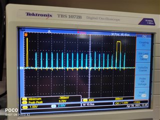
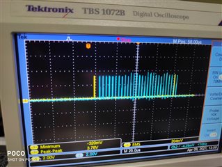
You can see DRDY pin (yellow) getting high, after 17th byte/ 25th byte of command frame. Transmission buffer data is in blue color. 

As it is making HIGH to LOW transition on DRDY pin, unnecessarily port interrupt is generated.

In hardware RESET/SYNC pin is tied to 3V3.

Thanks & Regards,

Nitin Kallole

  • Hello Nitin,

    Thank you for your post.

    Let's say we have set 16-bit word size. Now if we send command frame of length <17 bytes to AFE, it works properly.  if we send command of length >17 bytes to AFE, it didn't work. 

    Same happens for 24-bit word size.  Now if we send command frame of length <27 bytes to AFE, it works properly. For command of length >27 bytes to AFE, it didn't work. 

    It would be helpful to know more about what command you are sending and what you mean by "didn't work." Are you trying to read data, write to registers? What does the response in the next frame look like? Please send a capture of /CS, SCLK, DIN, and DOUT so that we can see what is sent in the frame and how the device is responding in the next frame.

    A typical frame consists of 10 words for the ADS131M08. This consists of 20 bytes for 16-bit word size or 30 bytes for 24-bit word size.

    Regards,

    Ryan

  • Hi Ryan,

    Thanks For Your Reply.

    I am attaching a document herewith. Please refer.

    drive.google.com/.../view

    Thanks & Regards

  • Thank you, Nitin.

    Can you please decode the MISO byte transfers in Figure 2 and 3?

    Also, what is the SCLK frequency used in each byte transfer?

    I'll continue to study the Word document and try to understand what is happening.

    Regards,

    Ryan

  • Hi Nitin,

    In Figure 4, it appears that you are not completing the frame before the next /DRDY interrupt. You must finish sending all 20 bytes within the data rate period. There are additional timing restrictions that require a minimum delay between the last SCLK falling edge and the /CS rising edge. Can you try increasing your SCLK frequency or reducing the delays between bytes?

    Regards,

    Ryan