Part Number: ADS54J66
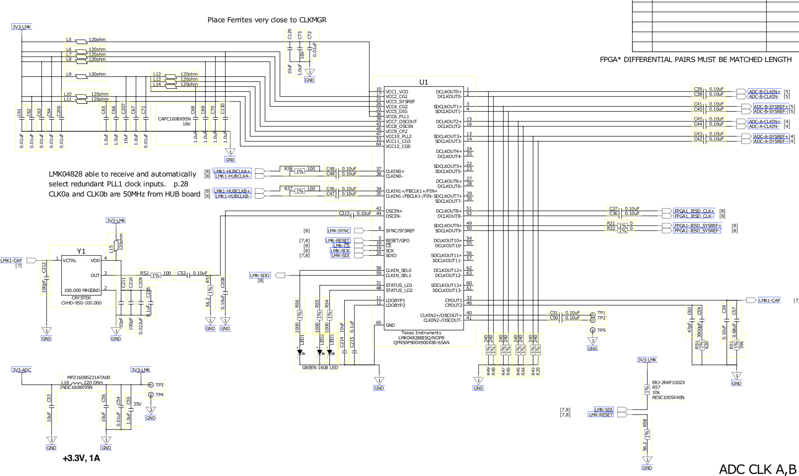
Other Parts Discussed in Thread: LMK04828,
Hi,
We have a custom PCB that hosts two ADS54J66s. For one of the ADCs we observe the expected behavior in all cases, we can configure and read back the configuration over SPI and everything agrees. The other ADC does not behave as well. It can be configured well enough to achieve JESD SYNC, but for things like enabling test patterns and/or turning off the interleaving correction the ADC responds inconsistently. The read back values are never what they should be and can be fairly inconsistent; sometimes you see values that are just one bit off of the expected value or sometimes the wrong register reads back the expected value. E.g. If I program ADC Page register 0x0F74 with a value of 0x40 to enable the test ramp, I can sometimes see the value 0x40 in register 0x0F6D. The same code is being used to program and read back each ADC. I've also used the same code to program the ADC on the ADS54J66EVM and had no problems. I've also probed, with an oscilloscope, the SPI signals at the ADC to make sure they looked okay, they did. This isn't just a problem with the read back either, I have had trouble getting this ADC to perform the JESD data scrambling or entering a test ramp mode.
We have two copies of this custom PCB, each with two ADCs - A and B. On each PCB ADC-A shows strange SPI behavior and ADC-B behaves well. However, for one of the PCBs ADC-A will sometimes read back some registers correctly, for the other PCB ADC-A basically never reads back anything correctly.
On each PCB the ADCs share all power rails so it seems unlikely that the issues might be due to an unreliable power rail.
I've investigated this issue to the extent that I'd be confident the issue is within the ADC chip, except for the fact that ADC-A on two different PCBs shows similar-ish unexpected behavior. That seems to indicate there ought to be some systematic issue with that chip on each PCB. We've spent a lot of time looking at the PCB layout & design associated with ADC-A and B to try and come up with a plausible explanation for what might be causing the observed programming issues and we've so far come up with nothing. The two ADCs are treated nearly identically in our design.
Right now we can achieve SYNC with the ADCs and read out data reliably, so the core ADC functionality seems to be working, but we're not confident enough to move forward with our design with this lingering issue unresolved. We'd prefer to avoid having to replace chips on our boards if that can be avoided, so I'm hoping someone here can tell me if there's anything I might be overlooking that could explain the behavior we're seeing. Or if there's some tests that could do that might indicate where the origin of this problem is. Or if people have seen issues similar to this in the past.
I'm happy to share some design files/screenshots or specific examples of the issues I mentioned if that'd be helpful.
Thanks,
Eric M