


Other Parts Discussed in Thread: DAC38RF80
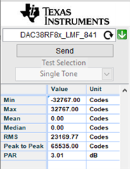
Dear Experts
I require some assistance with communicating with the DAC38RF80EVM + TSW14J56 in terms of producing two tones.
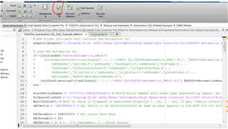
I have managed to find the relevant MATLAB files.
1) I managed to connect to the device using matlab in the following steps: MATLAB --> HSDC (This is where I can see the created Tone) ----> (HSDC to DAC38RF) (Is this step necessary)

2) If this step is necessary, after pressing the "Send button" on HSDC, where can I process this data straight onto the board to see the signal in my RF wave analyser. What settings need compiling on the DAC38RF software to download the waveform from MATLAB to the DAC?
3) How do I create a signal two tones using matlab example:
Channel 1: sin(2 Pi f1 t) + sin(2 Pi f2 t)
Channel 1: sin(2 Pi f1 t + Phi) + sin(2 Pi f2 t + Phi)
I see there is a path for collecting the excel traces which is not what I exactly want. Maybe you have an idea how I can change this and add the correct signals.

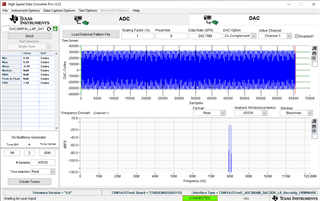
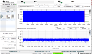
 Step one
 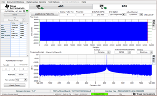 Step two
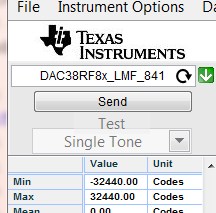 The "send button" should essentially send the signal to the DAC for me to use the signal as an output.
 STEP 1
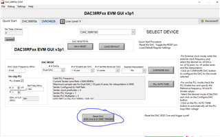 Step 2, button is pressed.
 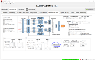 Step 3. The update NCO button is pressed for both DAC A and DAC B
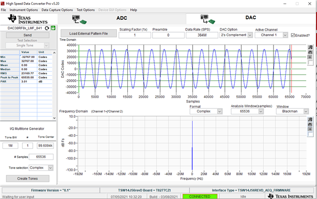 1) HSDC Pro
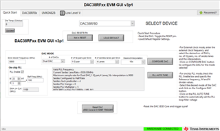
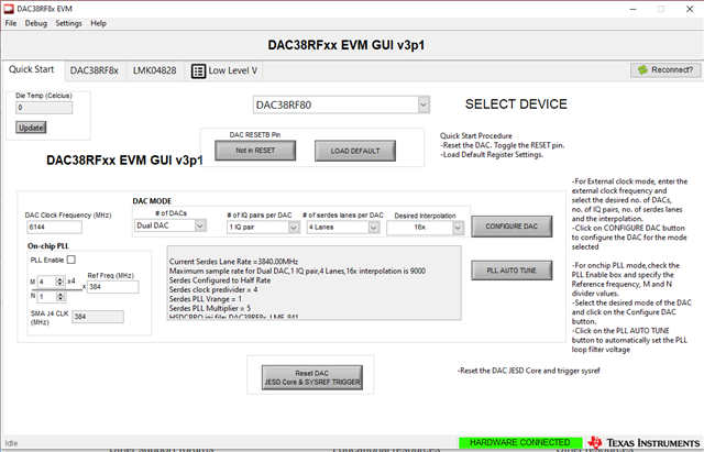 2) Quick start page DAC38RFx
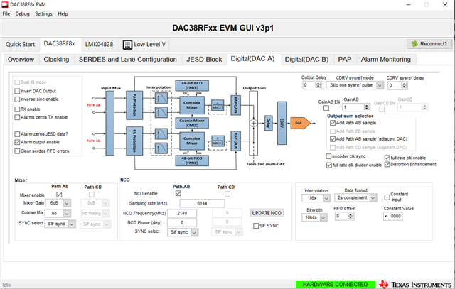 3) DAC A
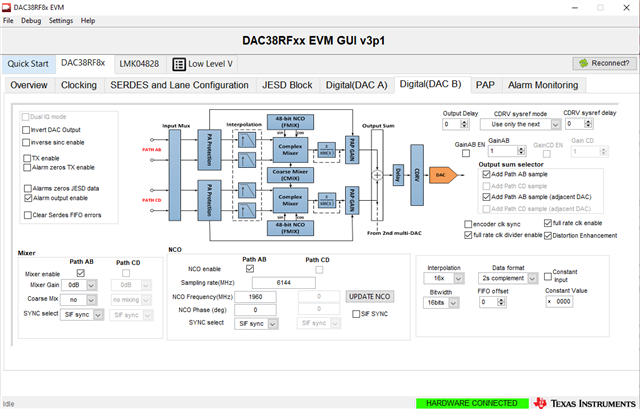 4) DAC B
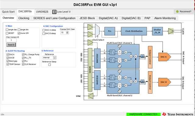 5) Overview
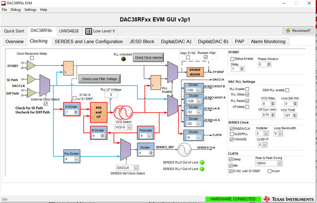 6) clocking. I am not using an external clock mode but rather would like to use the On board. I have tried it by unticking the "External clock select"
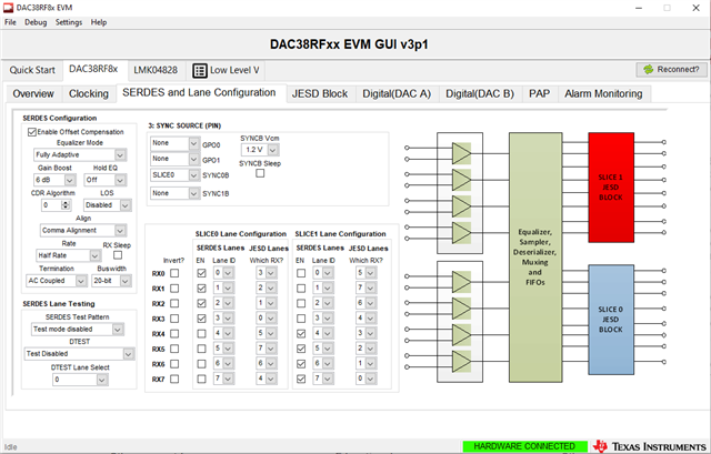 7) Serdes
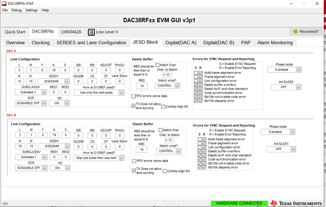 8) JESD block
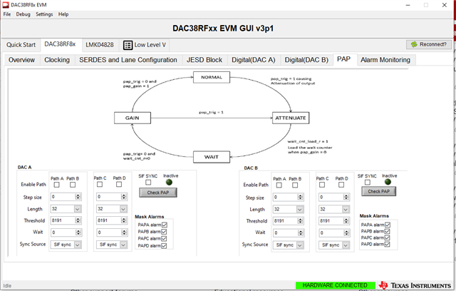 9) PAP
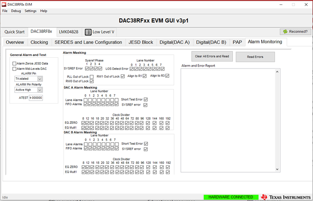 10) Alarm monitoring
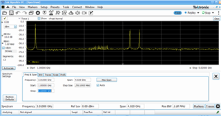
 1) First settings
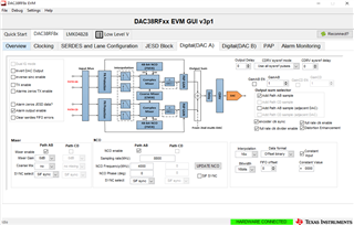 2) Second settings
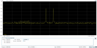 3) The waveform
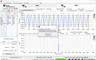 1) First
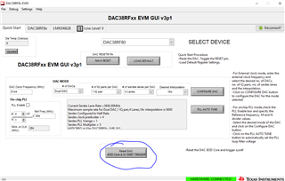 2)
2)  1) HSDC settings
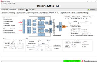 2) Mixer path AB is selected as well as NCO path AB for ( DAC A)
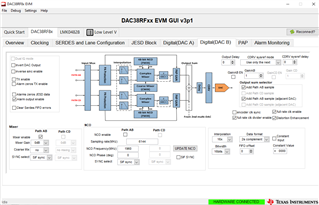 3 ) When I select NCO path AB the signal disappears from the output. I am also assuming the signal is incorrect.
 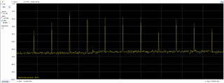 4 ) signal with the above settings
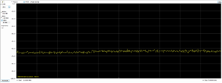 5) No signal following pressing of the NCO path AB setting to ON.