Other Parts Discussed in Thread: DAC8760,
Hello !
please can i have an information ;for DAC877, how much current consumption at 24V?
have you an exemple for an isolation circuit used for 'DA8775?
This thread has been locked.
If you have a related question, please click the "Ask a related question" button in the top right corner. The newly created question will be automatically linked to this question.
Mariem,
Current consumption varies depending on how the device is used (and what channels are used for what). How many channels will be used for current output and for voltage output? What ranges will be used? If you post that information, I may be able to give a better answer for the current consumption.
I don't know of any specific example designs with the DAC8775 using isolation. However, there is an example design using the DAC8760 that shows isolated digital and power sections. It's certainly possible to take elements from that design and apply it to work with the DAC8775. You can find information at the link below:
https://www.ti.com/tool/TIDA-00760
Joseph Wu
Thanks Joseph,
I'll use 4 channels for current output and for voltage output.
Output Current::±24 mA
Output Voltage:±12 V
DAC8775 is supplied by 24V
in this condition, what's the current consumption?
Is there a way to calculate the current consumption if I change the conditions?
Mariem,
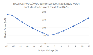
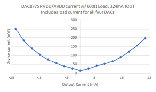
Again, there are quite a few things that affect the supply current. I did take some data for the device using a 600Ω load, with ±12V VOUT and ±24mA IOUT. Here are some plots for the PVDD/AVDD current in those modes of operation. Note that this current includes the load current being driven in to the load resistance.


I used the DAC8775EVM to take this data. If you need more detailed information about the current consumption of the device for your range of operation, I would definitely recommend getting the EVM. You would be able to take some measurements about the device power with these different modes of operation.
Joseph Wu
for clarification, you confirm that if the four channels are activated and supplied by 24V :
according to the curve: Iout= -24mA ==> Isupply=250mA . (4 channels activated at the same time)
Psupply total (for Iout= -24mA) = 24V*0.25= 6W
another question please, what is the impact of load on current consumption and the channel accuracy , if i change it?
Mariem,
I need to review this again, I may have sent you numbers for when AVDD/PVDD is 12V, so the amount of power might be significantly off. One question that I had was, what sort of load resistance do you expect to use for IOUT? Will there be a load resistance for VOUT?
Joseph Wu
Mariem,
The channel accuracy shouldn't change, but the current consumption might. This depends on the setting of the buck-boost converter as the supply adjusts to the load voltage (particularly in IOUT mode). I can run the setup to see what the current consumption is for that setting. I'll need a little time to run that test.
Joseph Wu
Mariem,
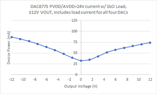
I did run the current with the in the VOUT mode with a 1kΩ load and it does look like this:

However, with the IOUT range of ±24mA, the IOUT is a bit high using a 1kΩ load. Ideally, the output would drive the load to ±24V. However, the VPOS_IN_x and the VNEG_IN_x is limited. You can see this in Table 1 of the datasheet.

Here, the datasheet says it's 20V, but its a bit closer to 22V. This limits the output to something below 20V. Regardless, IOUT with a 1kΩ load wouldn't be advised.
Joseph Wu