This thread has been locked.

If you have a related question, please click the "Ask a related question" button in the top right corner. The newly created question will be automatically linked to this question.

How did the 12-bits offset binary values be mapped to 8-bit characters in ADC12J4000EVM?

Other Parts Discussed in Thread: ADC12J4000EVM, ADC12J4000

Hi everyone,

I'm using ADC12J4000EVM to interface with our FPGA board.

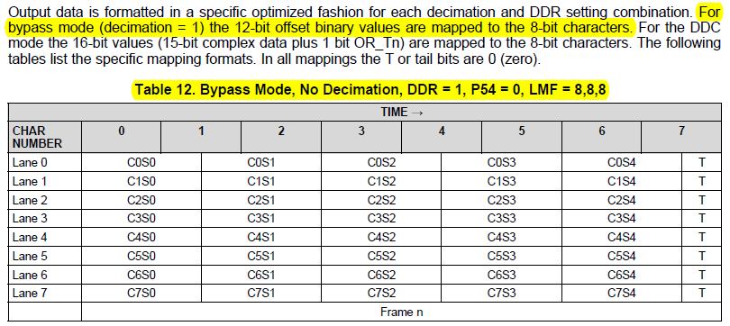
I read the datasheet of ADC12J4000, and I noticed that on page 40 it says:"For bypass mode (decimation = 1) the 12-bit offset binary values are mapped to the 8-bit characters."

I didn't understand how 12-bit could be mapped to 8-bit without loss of information, and I cannot find more detailed explanation of this. Can anyone explain it to me?

I want to get the 12-bit raw ADC data from the FPGA board. How can I recover 12-bit offset binary data from the 8-bit characters?

Thank you very much.

Regards,

Tong

  • Hi Tong

    The 12 bit samples are split at the 8-bit character boundaries. Here is an example showing the ADC test pattern data with the top table showing the 12 bit sample values, and the bottom table showing how these samples map into the 8 bit characters. I hope this helps make it more clear.

    Lane

    0

    1

    2

    3

    4

    5

    6

    7

    0

    1

    2

    3

    4

    5

    6

    7

    0

    0x000h

    0xFFFh

    0x000h

    0xFFFh

    0x000h

    0x0h

    0xFFFh

    0x000h

    0xFFFh

    0x000h

    0xFFFh

    0x0h

    1

    0x008h

    0xFF7h

    0x008h

    0xFF7h

    0x008h

    0x0h

    0xFF7h

    0x008h

    0xFF7h

    0x008h

    0xFF7h

    0x0h

    2

    0x010h

    0xFEFh

    0x010h

    0xFEFh

    0x010h

    0x0h

    0xFEFh

    0x010h

    0xFEFh

    0x010h

    0xFEFh

    0x0h

    3

    0x020h

    0xFDFh

    0x020h

    0xFDFh

    0x020h

    0x0h

    0xFDFh

    0x020h

    0xFDFh

    0x020h

    0xFDFh

    0x0h

    4

    0x040h

    0xFBFh

    0x040h

    0xFBFh

    0x040h

    0x0h

    0xFBFh

    0x040h

    0xFBFh

    0x040h

    0xFBFh

    0x0h

    5

    0x100h

    0xEFFh

    0x100h

    0xEFFh

    0x100h

    0x0h

    0xEFFh

    0x100h

    0xEFFh

    0x100h

    0xEFFh

    0x0h

    6

    0x200h

    0xDFFh

    0x200h

    0xDFFh

    0x200h

    0x0h

    0xDFFh

    0x200h

    0xDFFh

    0x200h

    0xDFFh

    0x0h

    7

    0x400h

    0xBFFh

    0x400h

    0xBFFh

    0x400h

    0x0h

    0xBFFh

    0x400h

    0xBFFh

    0x400h

    0xBFFh

    0x0h


    Lane

    0

    1

    2

    3

    4

    5

    6

    7

    0

    1

    2

    3

    4

    5

    6

    7

    0

    0x00h

    0x0Fh

    0xFFh

    0x00h

    0x0Fh

    0xFFh

    0x00h

    0x00h

    0xFFh

    0xF0h

    0x00h

    0xFFh

    0xF0h

    0x00h

    0xFFh

    0xF0h

    1

    0x00h

    0x8Fh

    0xF7h

    0x00h

    0x8Fh

    0xF7h

    0x00h

    0x80h

    0xFFh

    0x70h

    0x08h

    0xFFh

    0x70h

    0x08h

    0xFFh

    0x70h

    2

    0x01h

    0x0Fh

    0xEFh

    0x01h

    0x0Fh

    0xEFh

    0x01h

    0x00h

    0xFEh

    0xF0h

    0x10h

    0xFEh

    0xF0h

    0x10h

    0xFEh

    0xF0h

    3

    0x02h

    0x0Fh

    0xDFh

    0x02h

    0x0Fh

    0xDFh

    0x02h

    0x00h

    0xFDh

    0xF0h

    0x20h

    0xFDh

    0xF0h

    0x20h

    0xFDh

    0xF0h

    4

    0x04h

    0x0Fh

    0xBFh

    0x04h

    0x0Fh

    0xBFh

    0x04h

    0x00h

    0xFBh

    0xF0h

    0x40h

    0xFBh

    0xF0h

    0x40h

    0xFBh

    0xF0h

    5

    0x10h

    0x0Eh

    0xFFh

    0x10h

    0x0Eh

    0xFFh

    0x10h

    0x00h

    0xEFh

    0xF1h

    0x00h

    0xEFh

    0xF1h

    0x00h

    0xEFh

    0xF0h

    6

    0x20h

    0x0Dh

    0xFFh

    0x20h

    0x0Dh

    0xFFh

    0x20h

    0x00h

    0xDFh

    0xF2h

    0x00h

    0xDFh

    0xF2h

    0x00h

    0xDFh

    0xF0h

    7

    0x40h

    0x0Bh

    0xFFh

    0x40h

    0x0Bh

    0xFFh

    0x40h

    0x00h

    0xBFh

    0xF4h

    0x00h

    0xBFh

    0xF4h

    0x00h

    0xBFh

    0xF0h

    Best regards,

    Jim B

  • Hi Jim,

    Thank you very much.
    In this bypass mode configuration, LMF = 8,8,8. I knew that L means number of lanes, and F means octects per frame. M means number of (logical) converters, which equals to 8. I didn't understand the meaning of M.
    In my experimental setup, the input signal is a 100MHz sinusoid wave, and the ADC sample rate is 3760 MSPS. I thought I only have one converter and a single input signal.
    Could you tell me what's the meaning of logical converters? Is each logical converter corresponding to each lane?

    Regards,
    Tong
  • Hi Tong

    From a user standpoint this device is a single ADC. To comply with the JESD204B standard data mapping requirements, and provide an efficient implementation we use 8 logical converters. You are correct, basically we consider it as 1 converter per lane. This allows a very efficient mapping and transmission of the serial data.

    Using M=1 and strictly following the JESD204B standard would result in a less efficient implementation that would consume more power and have greater data latency.

    Table 12 shows how the data is mapped in the M=8 standard compliant format, with one converter per lane and 5 samples per converter per Frame. The sample labels are C#S# with C being the converter number and S being the sample number. We can consider these as 8 interleaved sub-converters, with C0 sampling earliest and C7 sampling latest.

    Table 13 shows how the customer should consider the same information for an M=1 converter, with 40 samples per Frame. S# is the sample number from earliest to latest within the frame.

    Best regards,

    Jim B

  • Hi Jim,

    Now I understood.
    Thank you so much.

    Regards,
    Tong
  • Hi Jim,

    I'm able to extract the ADC sampled data from FPGA and recover the raw data in matlab. 

    But I want to do some DSP processing of the sampled data in FPGA. So I want to recover the sampled data to 12bits in each lane.

    Could you tell me how to do this in FPGA efficiently? Does TI provide solutions for this?

    Thank you very much.

    Regards,

    Tong
  • Hi Tong

    Our FPGA firmware is a very flexible configurable design to allow us to support 8, 12, 14, 16, etc. resolution ADCs. Because of this it is not the most efficient to directly process the ADC12J4000 12 bit data.

    I think it would be best to contact your FPGA support team to get their recommendations.

    Best regards,

    Jim B

  • Hi Jim,

    Thank you very much.

    In my project I didn't use TI's FPGA firmware and I need to do DSP processing, so I want to know how to efficiently recover the 12 bit data in general FPGA design. I'm working on this project alone so I don't have a support team.

    Could you tell how to recover the 12 bit data efficiently without using TI's FPGA firmware? Or is there any example design to do this task?

    Regards,

    Tong

  • Hi Tong
    I will look into this and respond as soon as possible.
    Best regards,
    Jim B
  • Hi Tong

    I haven't located any example firmware that does the function that you need.

    In DDC Bypass mode, the data frame is 8 octets long (Five 12-bit samples plus 4 tail bits). After it is received and decoded, the serial data from each lane is output on a 32 bit wide bus, so half of the data frame comes out each bus cycle. The 32 bit bus outputs a new word for every 40 bits that are received on the link (before 10b8b decode). So the output rate is (8*10^9)40 = 200 MHz for a 4 GHz clock.

    You need to take every two 32-bit words and parse out the 12 bit samples, discarding the tail bits. Since the 12-bit sample rate is very high, once you have the 12 bit samples parsed you will need to send them to separate DSP processing blocks, to do the processing in parallel. For example if you split the data into 8 parallel streams, the sample rate of each stream is still 500 Msamples/sec.

    Best regards,

    Jim B

  • Hi Jim,

    Thank you very much.

    Now I'm able to create my own project to do the ADC data demapping.

    Regards,

    Tong