This thread has been locked.

If you have a related question, please click the "Ask a related question" button in the top right corner. The newly created question will be automatically linked to this question.

ADS124S08: Configuring for a single-ended measurement

Part Number: ADS124S08

I have a PCB using ADS124S08 for ratiometric measurement of two 4-wire RTD's. These use the pins AIN0-AIN05, REFP0, REFN0, REFP1/AIN6, REFN1/AIN7 and it works great (thanks to help I got in this forum).

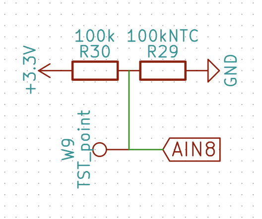
Connected to AIN8, I have a standard 100k NTC Thermistor (MPN: NB12SC0104JBB) that is connected as in the schematic below. When measuring with a multimeter on the test point W9, I get 1.67V. When I increase the temperature of the NTC, it rises and falls very precisely, so electronically all is good. My problem is measuring this with the ADC.

According to the datasheet, I've found that to do single-ended measurements, I have to set the PGA in BYPASS mode. I've also found that single-ended measurements should use AINCOM as a reference. AINCOM is connected to GND. I'm unable to find anything else that I have to do to make this work, but the readings are very low and do not reflect the temp in any way. I've also tried replacing AINCOM with AIN9 connected to GND, with no sensible results.

I suspect that there's just a single, tiny bit of info that I've missed in the datasheet that prevents the ADC from measuring AIN8, but I'm unable to find it. Can someone please help me set the registers right for single ended measurements on this ADC?

  • Jens,


    There shouldn't be much different about measurements with AIN8-AINCOM (as the AINP-AINN connections) than any of the other measurements that you've made. Both AIN8 and AINCOM can be set to just as any other input multiplexer setting for the ADS124S08. The only thing that is different is the setting for the reference. RTD measurements use a ratiometric measurement with an external reference input, while this thermistor measurement likely uses a voltage reference (probably using the internal voltage reference).

    There are still few things to check. I would start by verifying that both AIN8 and AINCOM are both properly connected on the board. Then check the multiplexer settings. The INPMUX setting should be 8C for AIN8 to AINCOM. The PGA register should be 00 to disable the PGA and bypass it and the REF register should be 1A. This would enable the reference and use it for the ADC. Then measure the reference to verify that it is on. Also, make sure the GPIO is disabled, so that AIN8 isn't accidentally used for a GPIO. Make sure that the VBIAS line isn't enabled and that the IDAC isn't going to either pin. If you've measured the thermistor output, you're probably ok though.

    After that, what type of readings are you getting out of the ADC? It might help to debug this if you post the ADC readings. If the readings are consistent, this might offer a clue. For any ADC, the output code is a result of the input measurement, the reference, and any gain that you might be using.

    If none of my comments help, it might be best to post a schematic of the circuit and try to get a reading of the configuration register when making the measurement.


    Joseph Wu
  • Thanks Joseph,

    I looked over the settings you mentioned and I'm not seeing what I expect. I'm currently in a room that is approximately 80F (26.7C) and the Thermistor measures at 1.529V to GND with a multimeter.

    My registers are now set like this:

    Register 0x00 = 0x08 (ID_ADDR_MASK)
    Register 0x01 = 0x00 (STATUS_ADDR_MASK)
    Register 0x02 = 0x8c (INPMUX_ADDR_MASK)
    Register 0x03 = 0x00 (PGA_ADDR_MASK)
    Register 0x04 = 0x14 (DATARATE_ADDR_MASK)
    Register 0x05 = 0x1a (REF_ADDR_MASK)
    Register 0x06 = 0x00 (IDACMAG_ADDR_MASK)
    Register 0x07 = 0xFF (IDACMUX_ADDR_MASK)
    Register 0x08 = 0x00 (VBIAS_ADDR_MASK)
    Register 0x09 = 0x01 (SYS_ADDR_MASK)
    Register 0x0a = 0x00 (OFCAL0_ADDR_MASK)
    Register 0x0b = 0x00 (OFCAL1_ADDR_MASK)
    Register 0x0c = 0x00 (OFCAL2_ADDR_MASK)
    Register 0x0d = 0x00 (FSCAL0_ADDR_MASK)
    Register 0x0e = 0x00 (FSCAL1_ADDR_MASK)
    Register 0x0f = 0x40 (FSCAL2_ADDR_MASK)
    Register 0x10 = 0x00 (GPIODAT_ADDR_MASK)
    Register 0x11 = 0x00 (GPIOCON_ADDR_MASK)

    The readings are consistent. The output does not vary if I heat the Thermistor. Some observations and readings:

    • If I turn the IDAC off as per the dump above (IDACMUX = 0xFF, IDACMAG = 0x00) the raw data reading I'm getting from the ADC is 128 (0x80)
    • If I turn the IDAC off, but leave the IDAC magnitude set (IDACMUX = 0xFF, IDACMAG = 0x05) the raw data reading I'm getting from the ADC is 32896 (0x80C0)
    • If I do not turn off the IDAC and leave it at the defaults I use with the PTC's (IDACMUX = 0x30, IDACMAG = 0x05), the raw data reading I'm getting from the ADC is 8421376 (0x808000)

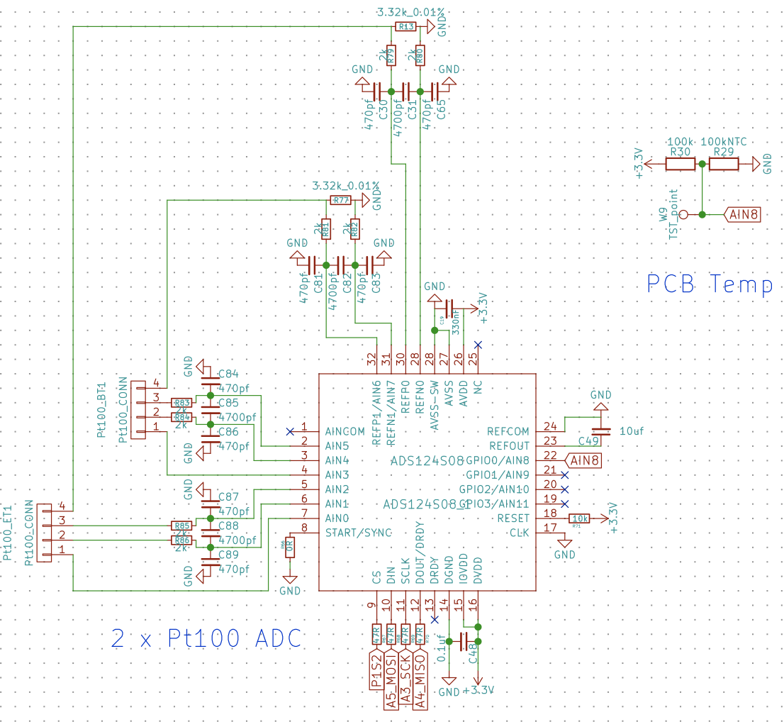
    I'm pretty sure that this is related to how my two RTD's are connected to the REF-pins, so here is the full schematic for the ADC + the Thermistor.

  • Jens,


    Looking at the schematic, AINCOM appears to be floating. If that is the case, then a reading from AIN8 to AINCOM won't give a real result.

    Luckily, you do have AIN7 connected to the GND node (through a 2kΩ resistor) and you should be able to use that. For the INPMUX register, try using 0x87 instead of 0x8C and check to see if you are able to get readings from the thermistor. I did briefly check through the remaining registers and they appear to be ok for that measurement.

    Let me know if that works. If you continue to have problems, post back and we can work on it again.


    Joseph Wu
  • Ahh... Sorry. Indeed, the PCB was made like this (with AINCOM floating). I've manually soldered a bodge wire from AINCOM to GND to fix that. Then again - I'd expect the output to change also if it was floating, so I do not think it's part of my problem?

    It's nighttime here in Norway now, so I'll test your suggestions first thing in the morning!
  • I had another go now with AIN7 set as the negative reference (0x87). The ADC still returns 128 (0x80). I also have AIN9 soldered to GND via a wire. I'm getting the same result for that combo.
  • Jens,


    Ok, I didn't realize that you had wired the AINCOM up. However, I'm a bit stumped. The circuit looks like it should work and I don't see anything wrong with the register settings for making the measurement. The settings of the IDAC should have no influence on the measurements of AIN8 to AINCOM if the internal reference is being used.

    I think it would be best to try to make a quick voltage measurement through other inputs just to see if this could be a board problem or code problem.

    First, the REFOUT voltage should be enabled and used by the ADC. Keep the reference on. With 10uF across REFOUT/REFCOM, it may take extra time to settle the reference if it is only used when sampling. You should measure with a multimeter that the reference is 2.5V.

    Now, I want to try to make a voltage measurement using the IDAC as a test. We'll use the IDAC to drive 50uA to AIN6. This current will go to R81 and R77. This should be 5.32k, and generate 0.27V across AIN6 to AIN7. You should also be able to measure that with a multimeter. Here are the registers that I think you'll need to change.

    Register 0x02 = 0x67 (INPMUX_ADDR_MASK)
    Register 0x03 = 0x00 (PGA_ADDR_MASK)
    Register 0x05 = 0x1a (REF_ADDR_MASK)
    Register 0x06 = 0x02 (IDACMAG_ADDR_MASK)
    Register 0x07 = 0x6F (IDACMUX_ADDR_MASK)

    This should give you a reading of something near D9E83h. If you don't see that, then either the voltage or reference is off. I'd measure the input again with a multimeter to make sure that it is correct. If you do see this reading, then the ADC has correctly made a voltage measurement using the internal reference.

    After that, you should just be able to set the input multiplexer to AIN8 to AINCOM with the following:

    Register 0x02 = 0x8c (INPMUX_ADDR_MASK)

    If this is the only change you make and you still get an unusual value, I would use the multimeter to verify the voltages across the thermistor and reference and the rest of the circuit.


    Joseph Wu

  • Hi Jens,

    Just to add to Joseph's comments, have you actually checked the voltage at the AIN8 pin of the ADS124S08?  I see you have a test point, but you really should verify that the same voltage is being seen at the device pin.  Make sure there is a good solder connection on that pin.

    Best regards,

    Bob B

  • Thanks Bob and Joseph. I nailed it now!

    The problem was that my code was toggling between the RTD readings and reading the Thermistor. Once I measured on REFOUT I could see it turning on/off. The voltage on AIN8 is correct, but this switching just won't work as the settling takes too long time. The 10uF cap is there per the Application note on ratiometric measurements and it does indeed look like it messes this up :-/

    If I only read the Thermistor, I can read the voltage correctly. If I try to toggle between RTD's and Thermistor, it goes bananas right away. I'll just have to find an analog pin somewhere else I guess?

  • Jens,


    I'm glad you got the source of your problem figured out. The reference does take some amount of time to settle as shown in Table 10 of the datasheet.

    I'm not sure how you have the system designed and if you need a low-power shutdown, but you can just leave the reference on (or just give it sufficient settling time). In the REF register, the REFCON[1:0] bits can be set to 10b. This will turn the internal reference on and leave it on.

    As I mentioned earlier, you might be able to use the AIN7 input as AINN instead of tying a wire from AINCOM to ground.


    Joseph Wu