This thread has been locked.

If you have a related question, please click the "Ask a related question" button in the top right corner. The newly created question will be automatically linked to this question.

ADS131A02: Initialization Issue

Part Number: ADS131A02


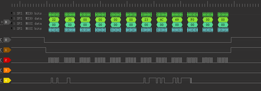
I am trying to initialize ADS131A02 as  the initialization process given in datasheet. First step mentioned in that is RESET. After sending RESET command (0x0011),i get 0xff02 .then Unlock ,ideally unlock should response a Unlock word (0x0655) but i am getting 0xff02 too .

I am operating ADC in 16 bit mode & with 84/32Mhz SPI clock.

I am unable to recieve Unlock word,whatever isend it just response 0xff02.

Kindly help or share some sample code,thanks alot!

  • Leonardo,

    First, I've taken the picture from the other post, closed the other post, and I'll show the picture below:

    You mention that M0 and M1 are floating, and M2 is grounded. This means that the device word size is 16 bits, and you are in synchronous slave mode.

    At this point I'm not sure what is wrong. However, the repeated FF02 response means that the device is not receiving the proper input command. The device's only response would be 0xFF02 until it receives an UNLOCK command 0x0655.

    Can you check to see if the DIN line that you are measuring actually makes it to the pin of the device? A bad solder or broken connection to DIN would have the same effect. If you are connecting the master to the device through separate boards, I would also check to make sure the master and slave have the same digital supply voltages and the same ground connection.

    Let me know if any of that works for you, if not, can you show a schematic and picture of your setup?

    Joseph Wu

  • A bad solder or broken connection it not happened! Is same digital supply voltages and the same ground connection is must in my schematic?

    VCC is 3.3 V,did the schematic have problem, and your advice,please?

    This is reset configuration ,seem like good but cnv should be high. do not know why it was low when tranmit data.CNV is gpio output  high in mcu.

    If I want use 16bit word slave mode .Is what I do right,and do you have any example code!

    Thanks a lot!

  • 24bit word is ok now,frankly speaking:The datasheet is hard to understand than others.
  • Leonardo,


    Are you saying that you are now able to communicate with the device by using a 24-bit word? Can you post the logic analyzer response from the device and verify your M0 to M2 pin settings?

    For the original post, I was pointing out that the device was not receiving the UNLOCK command. That is why I suggested a bad connection from DIN. If the device does not receive UNLOCK, then the 0xFF02 is the expected response. If device did not receive the UNLOCK command, then there is a problem with the communication and either the device isn't getting the proper command, or the digital timing is violated.

    Regardless, if you have gotten the device to respond then I'm glad you were able to communicate with the device. I would agree with you that this is a rather complex device and the communication is must be correct or the device does not behave as expected. I'll close this post for now, but if you are still having problems post back and we'll continue to review this.


    Joseph Wu
  • Yep. I change the M1 pin to gnd use 24bit word. now,I finish the inite of ADS131A02 refer to some guys code!

        while(ADS131_Reset() != 0xFF02); //reset
        while(ADS131_UnlockOrWakeup(UNLOCK_CMD) != UNLOCK_CMD);//unlock
        while(ADS131_Wreg(0x4BA8) != 0x2BA8);//A_SYS_CFG
        while(ADS131_Wreg(0x4C3C) != 0x2C3C);//D_SYS_CFG
        while(ADS131_Wreg(0x4D08) != 0x2D08);//CLK1   fICLK = fCLKIN(16.384mhz) / 8
        while(ADS131_Wreg(filter) != ((filter&0x0FFF)|0x2000));
                                          //CLK2  fMOD=fICLK/8    fDATA=fMOD/400   now is 5.12Khz
        while(ADS131_Wreg(0x5100) != 0x3100);//ADC1
        while(ADS131_Wreg(0x5200) != 0x3200);//ADC2
        while(ADS131_Wreg(0x4F0F) != 0x2F03);//Enable

    There have problem  i think should responce 0x2F0Factuallly it is 0x2F03.

    (datasheet:


    0000 : All ADC channels powered down
    1111 : All ADC channels powered up
    All other settings: Do not use


    )
        while(ADS131_UnlockOrWakeup(WAKEUP_CMD) != WAKEUP_CMD);//wakeup
        while(ADS131_Wreg(LOCK_CMD) != LOCK_CMD);//LOCK

    thanks for your help!

  • Hi

    why i can not read out correctly data use Synchronous Slave Mode Device Connections ! the first read line is status(STAT_1),then STAT_P,STAT_N,STAT_S。what’s the problem?done->DRDY

  • Leonardo,


    Synchronous slave mode is only used with a synchronous master. This could be a synchronous master microcontroller, but it is generally used as a daisy chained device that is being operated as a synchronous master. If you are only communicating with one device, then I would use the asynchronous interrupt mode. In that case you would be sending null commands each time the DRDY goes low to read the data.

    Regardless, in your plot it looks like you're sending in commands each time to read the registers. Every other frame, you're sending in 23, 24, and then 25. This triggers a read of the register. Instead can you send in a set of null commands to see if the data comes out correctly?


    Joseph Wu
  • Hi Joseph Wu,

    I have changed to asynchronous interrupt mode.

    Now,I can read outdata but the data readout cannot update go after input.  I adjust the input from 0~4V. I can read out data but the data sometime same to input sometime not. what i send is null commands.

    Nomatter 24bit *4 or 24bit*3 ,i can read out data but sometime same to input sometime not.

    How can I read out data same with input when the input changing.

  • Leonardo,


    I didn't realize that this post still had an open question. Have you been able to solve your communication issue for this device?


    Joseph Wu