This thread has been locked.

If you have a related question, please click the "Ask a related question" button in the top right corner. The newly created question will be automatically linked to this question.

DAC8760 schematic verification

Other Parts Discussed in Thread: DAC8760

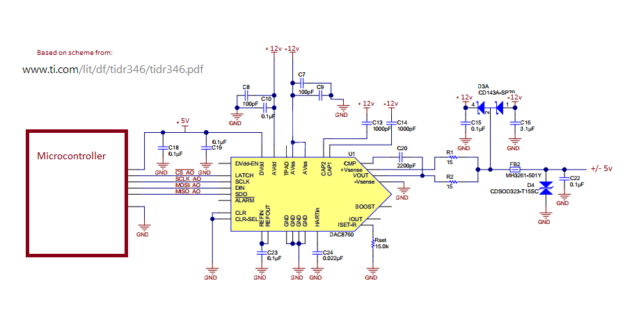
please check out this schematic that i edited based off of the schematic from http://www.ti.com/lit/df/tidr346/tidr346.pdf all I want is to be able to output + or - 5V (and maybe +-10v) commanded from a micro controller via serial control, I don't need the current output; so is it okay if i just disregard the current output pin? I changed the supply from +/- 15V to +/- 12​V  and I removed some caps from between, the now, -12V and AVss because that is how the datasheet showed it. do I need to connect TPAD to Avss?  if this Schematic will not work would you mind giving me some guidance?

thank you!
  • Hello Greg,

    Please pardon my delayed response, I was very sick and out of office most of last week.

    1. Leaving IOUT floating shouldn't be any problem. As an alternative you could connect it directly to GND, even if the current output is accidentally enabled a short-circuit condition is valid for the current output. I mention this because generally speaking if I'm going to put a design in a potentially noisy EMC/EMI environment I prefer to leave as few floating pins as possible to reduce possible coupling paths.
    2. I've had a hard time getting my hands on the ferrite beads I used in that design lately, I think they've been discontinued. Since then I've been using a very similar part, FBMH3225HM601NT from Taiyo Yuden with good success against the IEC transients. Also looking at trying 742792121 from Wurth, fairly similar but slightly smaller package. The ferrites are pretty easy to choose for this but I thought I would share these with you anyway to quickly help out if you have issues sourcing the other part.
    3. Looks like you're going to change the supply rails to +/-12V. That's fine, in terms of device operation for the DAC8760, but it does impact the protection circuitry in front of the device. Basically the TVS diode at D4 isn't going to be as effective as it was in the original design because the breakdown voltage is at 16.7V and the diodes at D3A will conduct well before the TVS, should be ~12.7V nominal (i.e. low current). Before the TVS kicks in the clamp-to-rail diodes are going to take most of the current, causing the forward voltage to rise, potentially exposing the DAC8760 to voltages that could cause damage. The same family of devices as D4 offers a part called CDSOD323-T12SC that has 13.3V breakdown that would be a much better fit in this modified design.
    4. Thermal pad should be connected to AVSS or floating. From a reliability standpoint, connecting it is better than floating it.

    Greg Spencer said:
     and I removed some caps from between, the now, -12V and AVss because that is how the datasheet showed it.

    Which figure are you referring to? Figure 91? If so, that's sort of a simplified diagram since it only shows a single AVSS pin. Each pin should have the same decoupling scheme, so I would suggest you add the capacitors back to the schematic.

    Please let me know if you have any further questions.

  • Thank you! this is very helpful. Also, I'm glad you are feeling better. 

    -so I take it I don't need to change the diode at D3A?

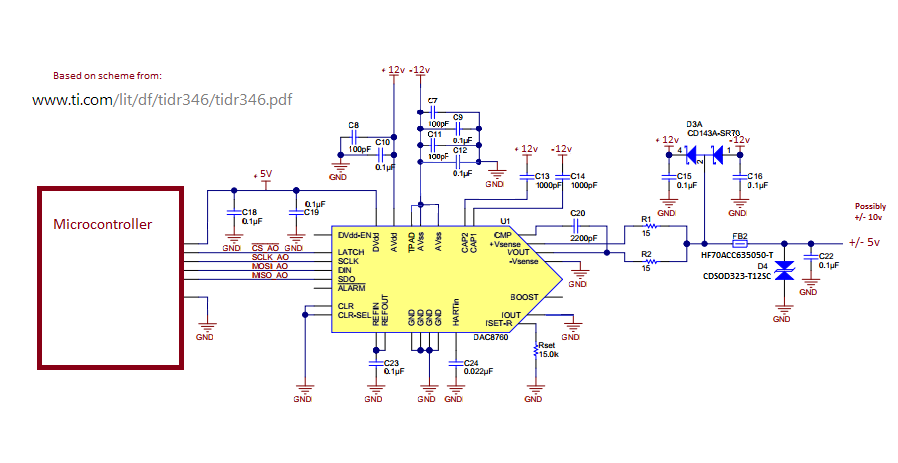
    -I put the caps back in C11, C12.

    -I sourced a 3A 500Ohm @100MHz with a DCR max of 40mOhm ferrite bead its called HF70ACC635050-T 

    -and changed D4 to the CDSOD323-T12SC

    Does this all look in order now? is the isolation between the microcontroller and the DAC preferred? would it be okay without it? here is the updated scheme:

  • Greg,

    Greg Spencer said:
    -so I take it I don't need to change the diode at D3A?

    Functionally, there is no need to. D3 is a dual channel array product, though, so if you're not using the other channel you might look for another product that is single channel only. Off the top of my head I don't have a part number for you at the moment. I can help you look for one if you'd like.

    Greg Spencer said:
    is the isolation between the microcontroller and the DAC preferred? would it be okay without it?

    The need for isolation is really defined by your system and the use-cases you expect your system to be exposed to. We included the digital isolation in that design just to point folks to an option for digital isolation if the part was being designed into an input isolated system.

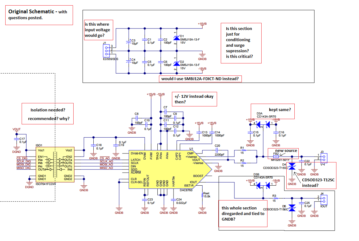
  • also here is a picture of the original schematic with questions highlighted. I thought it would make it all more clear than bullet points.

  • okay, I would be using the + and - 12v so I would use the same diode.
    thank you for the suggestion on the isolation. it helped me see that we will need it.
  • Greg,

    When the clamp-to-rail diodes D3A and D3B are forward biased by a transient on the output pins, current is going to pass into the power supplies. Depending on the structure of your power supply solution, you will need somewhere to source/sink current to keep the voltage at a level that is safe for the DAC8760 and the power supply solution itself. In most cases, you're going to want the TVS diode in place still.

  • right, I did intend on keeping the diodes. I was just wondering if the change from 15 to 12v and the output being somewhere between +/- 10v made a difference on D3A. So, since I only need 1 channel, would the part number DDSL01-030SL work? its:


    -I guess all that is left are the questions about the diodes and caps around the voltage input (D1 and D2) in the original schematic I posted above ^up there with the red boxes^

    -thank you for your time!

  • Greg,

    My previous post, quoted below for clarity, was directed at the red box around diodes D1 and D2. Sorry that wasn't clear.

    "When the clamp-to-rail diodes D3A and D3B are forward biased by a transient on the output pins, current is going to pass into the power supplies. Depending on the structure of your power supply solution, you will need somewhere to source/sink current to keep the voltage at a level that is safe for the DAC8760 and the power supply solution itself. In most cases, you're going to want the TVS diode in place still."

    The capacitors are optional, they're just bulk board-level decoupling / charge well capacitors. You would change those diodes to a lower breakdown voltage variant from that family.

    The diode you've linked looks good.
  • I understand now. Thank you!