This thread has been locked.

If you have a related question, please click the "Ask a related question" button in the top right corner. The newly created question will be automatically linked to this question.

Converting Output code to voltage

Other Parts Discussed in Thread: ADS1292

Hi,

In a similar post I saw this answer for converting output code of ADS129X to voltage:

"The most straightforward way to convert your output codes back into input voltage is to AND the data with 0x800000 and test the MSB (most-significant bit). If the MSB equals 0, simply multiply the decimal equivalent by the LSB size. If the MSB = 1, you must first subtract 2^n from the decimal equivalent, then multiply by the LSB size. "


I have a few questions. 

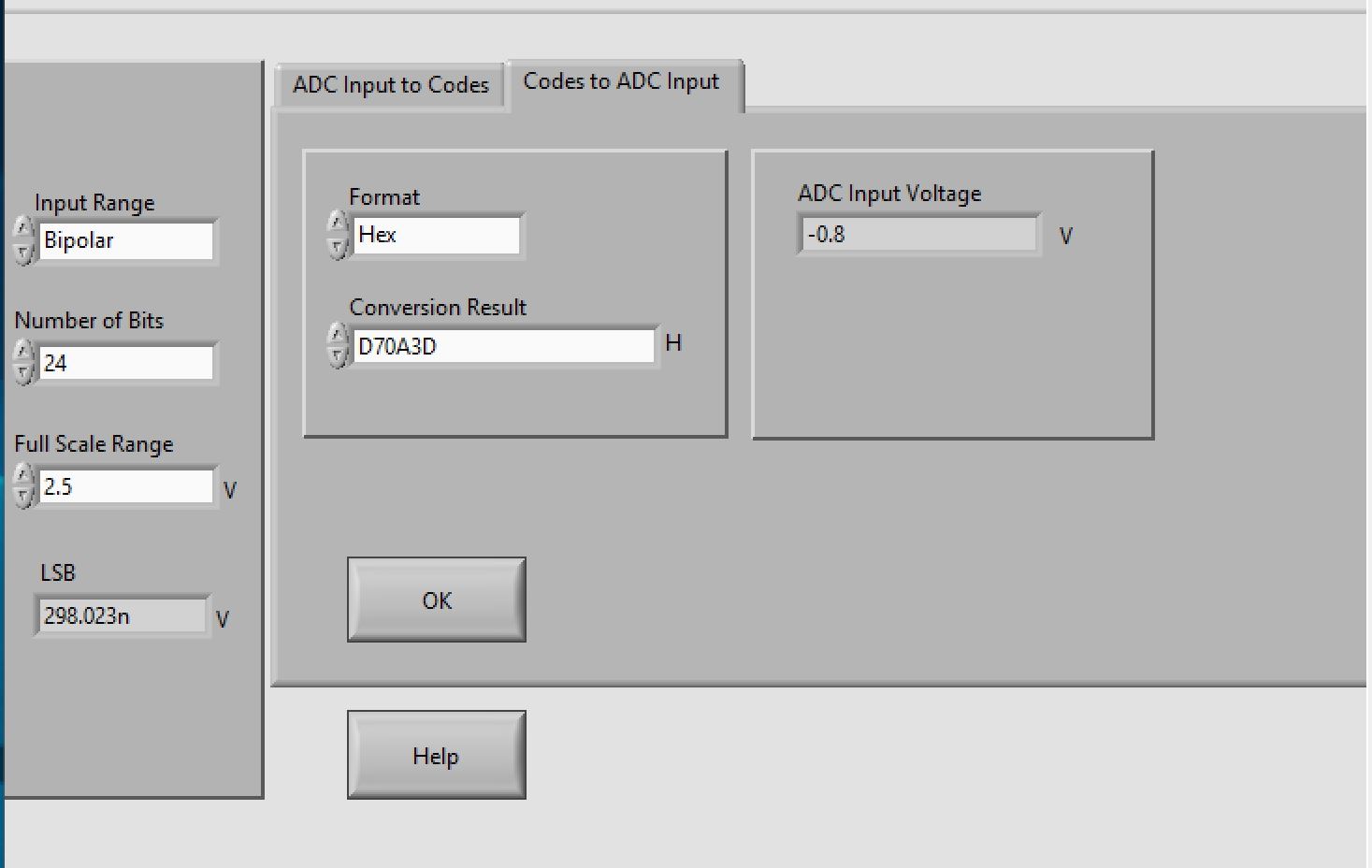
1. So if my ADS output code from channel 1 is, let's say '0xD70A3D'. I should AND this code with 0x800000 as shown below:

A = 0xD70A3D & 0x800000

2. He says to test the MSB, that is I need to check the MSB of 'A' right?

3. Now, if the MSB is 0, I have to multiply the decimal equivalent by LSB

My question here is, should I multiply the code (0xD70A3D) or the result of AND (A) with the LSB to get the voltage?

Thank you

  • Hi Harikishore,

    The 'AND' ing is just testing the MSB for a 1 or 0.  If you take 0x800000 'AND' 0xD70A3D, you end up with 0x800000.  The MSB is the sign bit => if it's 1, you have a negative number, if its not, it's positive.

    With the 0xD70A3D number, the MSB is a 1, so you know its a negative value.  You would then subtract 0xD70A3D from 0xFFFFFF to get 0x28F5C2, which is 2,684,354 in decimal.  Multiply that number by your LSB size (of 74.506 NV in this example) and then apply the sign to get the -200 mV from the example that Alex provided.

  • Hello,

    In addition to Tom's good answers, you may find the Analog Engineer's Calculator useful.  In the "Data Converter" section you'll find a "Code to Voltage" (or vice versa) calculation tool.  The unipolar option assumes a straight binary output and the bipolar output format uses standard binary 2's complement like your question is about.

    http://www.ti.com/tool/ANALOG-ENG

  • This is great! I got confused with the XOR operation mentioned in a similar post. Yes, the AND operation provides 0x800000 if the code is negative and 0 if the code is positive. Then I have to check the MSB as follows:
    If(A<<23==1)
    {
    Then subtract (2^n-1) from the decimal equivalent of the code and multiply by the LSB size
    }
    And if the MSB is 0, I just have to multiply by the LSB size. This gives me an answer. 
    Also I believe, the ADS1292 evaluation board uses 3v supply and hence the vref is 2.42. Therefore, LSB = (2 x 2.42) / gain/ 2^n
    I struggled to convert the code to its correct decimal value initially. I stored the input code as unsigned long and later to convert the code back to voltage, the code changed its decimal value. I then stored the code to a signed long variable used this variable further down in the program for conversion and it worked! This is because the Arduino doesn’t have a 24-bit variable. 
    The only question I have now is in the incoming code. I receive 3 bytes of each code into a pointer and then store them to 8-bit variables as below:
    adccode1, adccode2 and adccode3. Then uses shift and OR operator to get the code back. like adccode3<<16 | adccode2<<8 | adccode3. 
    I think this is correct. However here: https://e2e.ti.com/blogs_/archives/b/precisionhub/archive/2016/04/01/it-s-in-the-math-how-to-convert-adc-code-to-a-voltage-part-1, the author ANDed each 8 bit segment with 0xFF. Is it something I need to look into?
    Thank you
  • Hi, Collin

    Thank you for this. But it seems the link is not working. It would be of great help if I could use this calculator to verify my conversions. Please help me with this.

    Thank you

  • Hi Harikishore,

    Try this link to the Analog Engineer's Calculator, and you don't necessarily have to do the extra step of ANDing each byte with 0xFF.  You should still get the same results.

  • Thank you so much! I appreciate your quick response. 

    As Alex said, VREF = 2.5 V, N = 24 bits, and Gain = 4, we can calculate the LSB size as 74.506 nV. An output code of 0xD70A3D would correspond to an input voltage of -200 mV. 

    I have attached a screenshot of the Analog Engineers Calculator with this post. 

    Here, the LSB is calculated as 298 nV. This is because the GAIN=4 is ignored here. However, we get ADC input voltage as -0.8 V. I found that if I divide the ADC input voltage by the gain, I get -0.2 V which is correct (=-200 mV).

    Hope this is correct. Thank you.

  • You've got it right!  The calculator does not realize the PGA gain, so if you divide the 298.023 nV and the -0.8 mV numbers in the calculator both by 4, you get the expected results.

  • Hi Thank you. 

    In Alex's example, he took VREF= 2.5 V, therefore, FSR= 2x2.5= 5 V. However in the screenshot above, I have taken FSR= 2.5. Is that a mistake or does the software recognise that it is VREF and multiply it by 2. 

  • In bipolar mode, the calculator assumes +/-Vref is your FSR.

  • Thank you. This helps!