


Other Parts Discussed in Thread: PCM5122, PCM5242
Dear TI-Forum,
I am currently working with the pcm5122. Every time I start audio playback, a click is audible. I read the datasheet a lot of times, but maybe I am missing something.
So far I can reduce the problem to the transition from standby to normal operation. The click is also audible, if I play “silence”.
My setup:
- The data is sent from an ARM CPU to the pcm5122 by I2S.
- DAC runs in VREF mode
- The DAC is BCK and LRCK master
- My input clock is a non-audio clock at 28 MHz. The clock is connected to GPIO5, converted by the PLL, output at GPIO3 and externally connected to SCK. This is described in this post --> http://e2e.ti.com/support/data_converters/audio_converters/f/64/t/267830#pi316685=2
- The problem stays the same, no matter if I use standby or power down
- The problem stays the same if I use the DAC as BCK master and LRCK slave
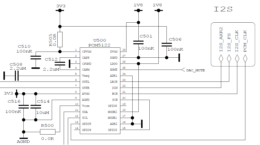
The schematic is the following:
I also have some images measured from the I2S and output of the DAC. Please note that the Y-axis is not correctly scaled.
1. If I send the DAC to powerdown and wake it up before sending audio data, I can see the PLL settling to the input clock.

If I only send the DAC to standby and not to powerdown, BCK and LRCK are present all the time. The rest of the behavior is the same. I also get the click if I only use standby and not power down. For better visualization I use power down and sine here, so you better see the timing.
2. There are multiple things to see after the PLL settled.
(1) wake up from power down
(2) square signal, approx. 4 ms after (1), the data sheet states 4 ms from start of clocks to release of internal reset
(3) spike, probably the audible click
(4) some noise, probably after unmuting, stops after elapsed time for auto mute
(5) less noise, auto muted
(6) spike at begin of I2S data, probably another click
(7) sine from audio data
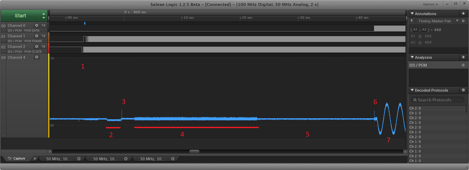
If I play “silence” instead of sine (I2S data stay at zero), I still see the points 2 – 5.
The used configuration is the following. The columns are
{Register, bits to set, bit mask}. For example { 0x08, 0x0C, 0x3F } means register 0x08, bits 0x3F are cleared and 0x0C are set.
{ 0x08, 0x0C, 0x3F }, // Reg 8 - GPIOs enable
{ 0x09, 0x11, 0x11 } // clock master
{ 0x0C, 0x03, 0x03 }, // Reg 12 - Master mode BCK, LRCLK reset (0x7F)
{ 0x0D, 0x30, 0xFF }, // Reg 13 - PLL clock source select (GPIO input) // not documented in data sheet
{ 0x12, 0x04, 0xFF }, // Reg 18 - PLL clock source select (GPIO input) // not documented in data sheet
{ 0x14, 0x01, 0x0F }, // Reg 20 - PLL dividers P divider (P=2)
{ 0x18, 0x00, 0x0F }, // Reg 24 - PLL dividers R divider (R=1)
{ 0x25, 0x04, 0xFF }, // Reg 37 - Ignore some errors / AutoClock off
{ 0x3D, 0x70, 0xFF }, // default volume
{ 0x3E, 0x70, 0xFF }, // default volume
{ 0x3F, 0x22, 0xFF }, // Reg 63 - Digital volume ramp speed
{ 0x52, 0x10, 0xFF }, // GPIO (from TI forum)
{ 0x53, 0x0A, 0x0F }, // GPIO
Then at page 0xFD, enable flex clock
{0x3F, 0x11, 0x00}
{0x40, 0xFF, 0x00}
Clock setting for 44100 Hz (probably does not matter for this problem)
{ 0x15, 0x06, 0x3F} // 21 PLL setting
{ 0x16, 0x25, 0x3F} // 22 PLL setting
{ 0x17, 0x02, 0xFF} // 23 PLL setting
{ 0x1B, 0x01, 0x7F} // 27 DSP source clock devider
{ 0x1C, 0x0F, 0x7F} // 28 DAC clock devider
{ 0x1D, 0x03, 0x7F} // 29 CP clock devider
{ 0x1E, 0x07, 0x7F} // 30 OSR clock devider
{ 0x22, 0x00, 0x03} // 34 fs speed
{ 0x23, 0x04, 0xFF} // 35 + 36 DSP clock cycles per frame
{ 0x24, 0x00, 0xFF}
Can you give me any hint where to do any further research to avoid the click?
