This thread has been locked.

If you have a related question, please click the "Ask a related question" button in the top right corner. The newly created question will be automatically linked to this question.

ADS1147: 3 point vs. 2 point calibration to correct gain and offset errors

Other Parts Discussed in Thread: ADS1147

Hi all,

I am using a ADS1147 with a Class A PT-100 RTD with a 4 wire configuration. I have been doing research into correcting gain and offset errors and calculating the offsets I need to refine the measuring accuracy on my system. I have seen a number of resources on using two points to calculate the offsets, but I have yet to see one for a 3 point calculation. Is there such a method out there? and if so, would it be any more accurate over a two point calibration?

  • Hi Max,

    What offset are you calculating, is it system or ADC?  And how are you making use of the data as a part of your measurement? 

    You really shouldn't be seeing system offset unless you have filter mismatch with your analog filtering.  For the ADC it is best to use the SELFOCAL.  This will take multiple measurements and average them.  Noise with any measurement needs to be minimized as it will affect the result.  Reissuing the SELFOCAL from time to time is a simple way to keep any offset drift affect of the ADC to a minimum. 

    The overall benefit of the SELFOCAL is that it is a background process that updates the values of the OFC registers.  The output code is automatically adjusted based on the OFC registers.  You should always issue the SELFOCAL at startup as a very minimum.

    Best regards,

    Bob B

  • Thanks Bob,

    What do you mean by system? Are you talking about the probe and ADC together?

    For calibration, I take two ADC measurements at different temperatures and calculate the offsets based off of those two points.

  • Hi Max,

    Yes, system is everything together.  Maybe I'm misunderstanding what you are truly asking.  Do you mean offset from a specific temperature?  Or do you mean offset relative to what the ADC is seeing from a shorted input case.  I've been discussing the latter.  If the ADC is set to have a zero offset (0 input results in 0 output), then the temperature can be above or below the expected due to gain or linearity errors. 

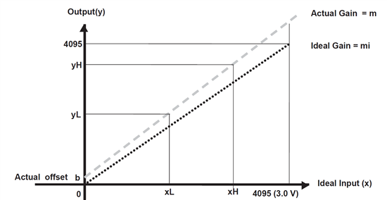
    Gain slope for the transfer function can be easily calculated with a two point calibration (rise/run).  If you think of the slope of a line with a X-Y graph it is simply Y= mX + b, where in the case of the ADC the analog input voltage value is X, the gain slope is m and the offset is b.  In the figure below you can visualize the transfer function for a two point calibration.

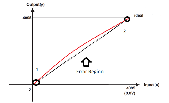
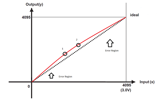
    This is ok if your measurement remains perfectly linear, but let's visualize what happens with a two point measurement if the repsonse is non-linear in the next two figures.

    Above would be similar to a system calibration where you have one point with a 0 or the shorted input case, and the other is with a full-scale input case.  As you can see you have error in the middle.


    In the above figure you see what can happen if you calibrate in the middle.  Now you have error in the measurement on either side of the calibrated region. What you are left with is to calibrate in more regions to create a piece-wise linear correction.  The more pieces you have, the closer it represents the actual curve.  Obviously there is a practical limit to this.

    Hope this helps,

    Bob B