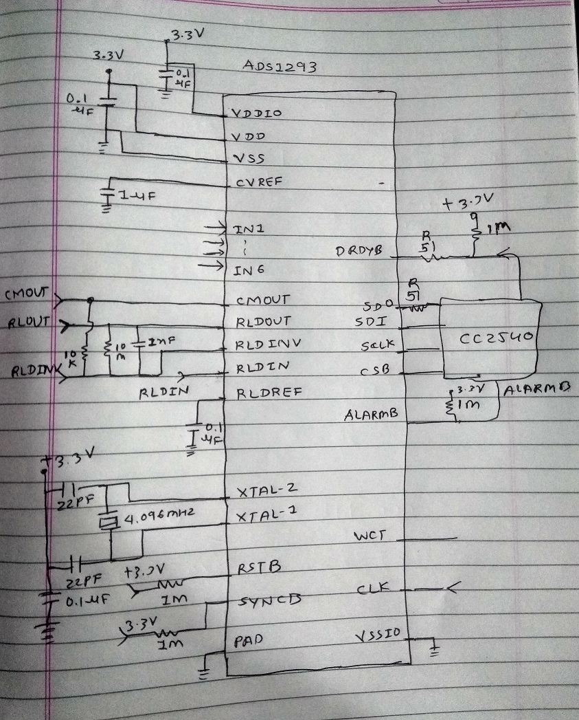
Any one got ADS1293 SPI communication with CC2540.
We want to read Revision ID 0x40 Register from ADS1293.
Lots of try but can not success to read Register.
Check CLK MOSI and CS Pin signal on Oscilloscope its Ok but not a any siganl Receive on MISO pin.
* INCLUDES
*/
#include <hal_types.h>
// Include Name definitions of individual bits and bit-fields in the CC254x device registers.
#include <ioCC254x_bitdef.h>
// Include device specific file
#if (chip==2540)
#include "ioCC2540.h"
#elif (chip==2541)
#include "ioCC2541.h"
#elif (chip==2543)
#include "ioCC2543.h"
#elif (chip==2544)
#include "ioCC2544.h"
#warning "The CC2544Dongle is not supported for this software example."
#warning "This code illustrate how to set up the SPI interface on the CC2544 device."
#elif (chip==2545)
#include "ioCC2545.h"
#else
#error "Chip not supported!"
#endif
#define SPI_BAUD_M 0
#define SPI_BAUD_E 16
void spiWriteByte(uint8 write)
{
U0CSR &= ~0x02; // Clear TX_BYTE
U0DBUF = write;
while (!(U0CSR & 0x02)); // Wait for TX_BYTE to be set
}
void spiReadByte(uint8 *read, uint8 write)
{
U0CSR &= ~0x02; // Clear TX_BYTE
U0DBUF = write;
while (!(U0CSR & 0x02)); // Wait for TX_BYTE to be set
*read = U0DBUF;
}
void TI_ADS1293_SPIWriteReg(uint8 addr, uint8 value)
{
uint8 inst;
P0_4 = 0; // /CS enable
inst = 0X7F & addr; // register address
spiWriteByte(inst); // Send register address
spiWriteByte(value); // Send data value
P0_4 = 1; // /CS disable
}
uint8 TI_ADS1293_SPIReadReg(uint8 addr)
{
uint8 pVal, inst;
P0_4 = 0; // /CS enable
inst = 0X80 | addr; // register address
// WAIT_1_3US(2); // Wait
spiWriteByte(inst); // Send lower register address
spiReadByte(&pVal, 0xFF); // Read data
P0_4 = 1; // /CS disable
return pVal;
}
void main(void)
{
/***************************************************************************
* Clock setup
CLKCONCMD = (CLKCONCMD & ~(CLKCON_OSC | CLKCON_CLKSPD)) | CLKCON_CLKSPD_32M;
while (CLKCONSTA & CLKCON_OSC);
// Note the 32 kHz RCOSC starts calibrating, if not disabled.
/***************************************************************************
* Setup I/O ports
*
* Port and pins used USART0 operating in SPI-mode are
* MISO (MI): P0_2
* MOSI (MO): P0_3
* SSN (SS) : P0_4
* SCK (C) : P0_5
*
*/
#if (chip==2540 || chip==2541 || chip==2543 || chip==2545)
// Configure USART0 for Alternative 1 => Port P0 (PERCFG.U0CFG = 0);
PERCFG = (PERCFG & ~PERCFG_U0CFG) | PERCFG_U0CFG_ALT1;
#endif
#if (chip==2540 ||chip==2541 || chip==2543 || chip==2545)
// Set pins 2, 3 and 5 as peripheral I/O and pin 4 as GPIO output.
P0SEL = (P0SEL & ~BIT4) | BIT5 | BIT3 | BIT2;
P0DIR |= BIT4;
#elif (chip==2544)
// Set pins 1, 2 and 3 as peripheral I/O and pin 0 as GPIO output.
P0SEL0 = 0x10; // Map P0_1 as UASRT0 SPI and P0.0 as GPIO.
P0SEL1 = 0x11; // Map P0_3 and P0_2 as UASRT0 SPI.
PDIR |= PDIR_DIRP1_0; // Set P1.0 as output.
#endif
/***************************************************************************
* Configure SPI
*/
// Set USART to SPI mode and Master mode.
U0CSR &= ~(U0CSR_MODE | U0CSR_SLAVE);
U0BAUD = SPI_BAUD_M;
U0GCR = (U0GCR & ~(U0GCR_BAUD_E | U0GCR_CPOL | U0GCR_CPHA | U0GCR_ORDER)) | SPI_BAUD_E;
TI_ADS1293_SPIWriteReg(0x00,0x01);
int x;
while(1)
{
x = TI_ADS1293_SPIReadReg(0x40);
}
Not a any data receive in x but its still 0x00.
what is problem?? we use CC2540 and ADS1293


