This thread has been locked.

If you have a related question, please click the "Ask a related question" button in the top right corner. The newly created question will be automatically linked to this question.

ADS1282: Continuous-sync mode with Sync clock

Part Number: ADS1282


Continuous-sync mode with Sync clock does not work.
DOUT always outputs 0.

ADS1282 settings are as follows.
- CONFIG0 Register: 0xC2 Continuous SYNC mode, 250SPS, Sinc + LPF filter.
- RDATAC command
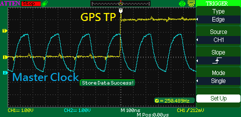
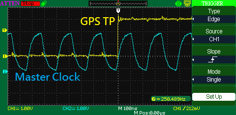
- Sync signal: GPS TP(Time pulse) signal 250Hz.(This signal is very precious sync signal.)

If the GPS TP signal is not input, DOUT is output normally.
I changed the sync signal to a different value and tried to input it as the original value, but it still does not work. (ex: 300Hz -> 250Hz)

I want to operate it as in Figure 48 on page 23 of the datasheet, but it does not work.

Best Regards,

KJ Park.

  • I found the above regarding the SYNC signal timing.

    In the fourth item, the timing of the SYNC pin is fairly strict.

    The master clock input is 4.096 MHz and the Sync signal uses the GPS module's Time pulse output signal.

    (The data output rate of ADS1282 is 250SPS and the frequency of the SYNC signal is 250 Hz)

    In this case, will continuous sync mode work normally? Or will the re-synchronization occurs?

    Thanks in advance for your help.

    KJ Park.

  • Hi KJ,

    The 250 Hz data rate and 250 Hz SYNC pulse should work as long as the master clock to the ADC is stable and not significantly altering the data rate.

    One important thing to note about continuous-sync mode from Figure 48, is that the SYNC rising edge should correspond to the falling edge of the ADC's master clock to ensure that the synchronization occurs. Do you have the ability in your MCU/FPGA to time the SYNC rising edge to the CLK falling edge?

    Best regards,
    Chris
  • Hi Chris,

    Thank you for the answer.
    As you can see in the picture above, there is drift between GPS TP signal and master clock.
    Therefore, the SYNC rising edge may not match the falling edge of the ADC's master clock.
    (The master clock uses a 4.096 MHz oscillator, and the GPS module uses its own internal clock.)

    In the figure, the master clock looks like a sine wave because of a bad probe.
    Actually, it is outputted as a square wave.

    Best Regards,
    KJ Park.

  • Hi KJ,

    Unfortunately, if these clocks are drifting too much with respect to one another then continuous-sync mode will regularly re-sync the device. If the drifts of each clock are smaller, then re-sync will occur less often; however, this mode really works best when the SYNC clock and ADC master clocks are derived from the same clock source.

    For continuous sync mode, do you have multiple ADC's in your system that need to stay synchronized, or do you just need to ensure that the ADC is operating at a very accurate data rate?

    Perhaps there is an alternative way of using your MCU to "re-clock" the GPS pulse so that the SYNC pulse and ADC clocks are derived from a similar source. To do this, you would likely need to create the ADC clock from your MCU clock. If this is not an option, then likely using pulse-sync mode in one way or another would be the next best option.

    Best regards,
    Chris