This thread has been locked.
If you have a related question, please click the "Ask a related question" button in the top right corner. The newly created question will be automatically linked to this question.
Hello
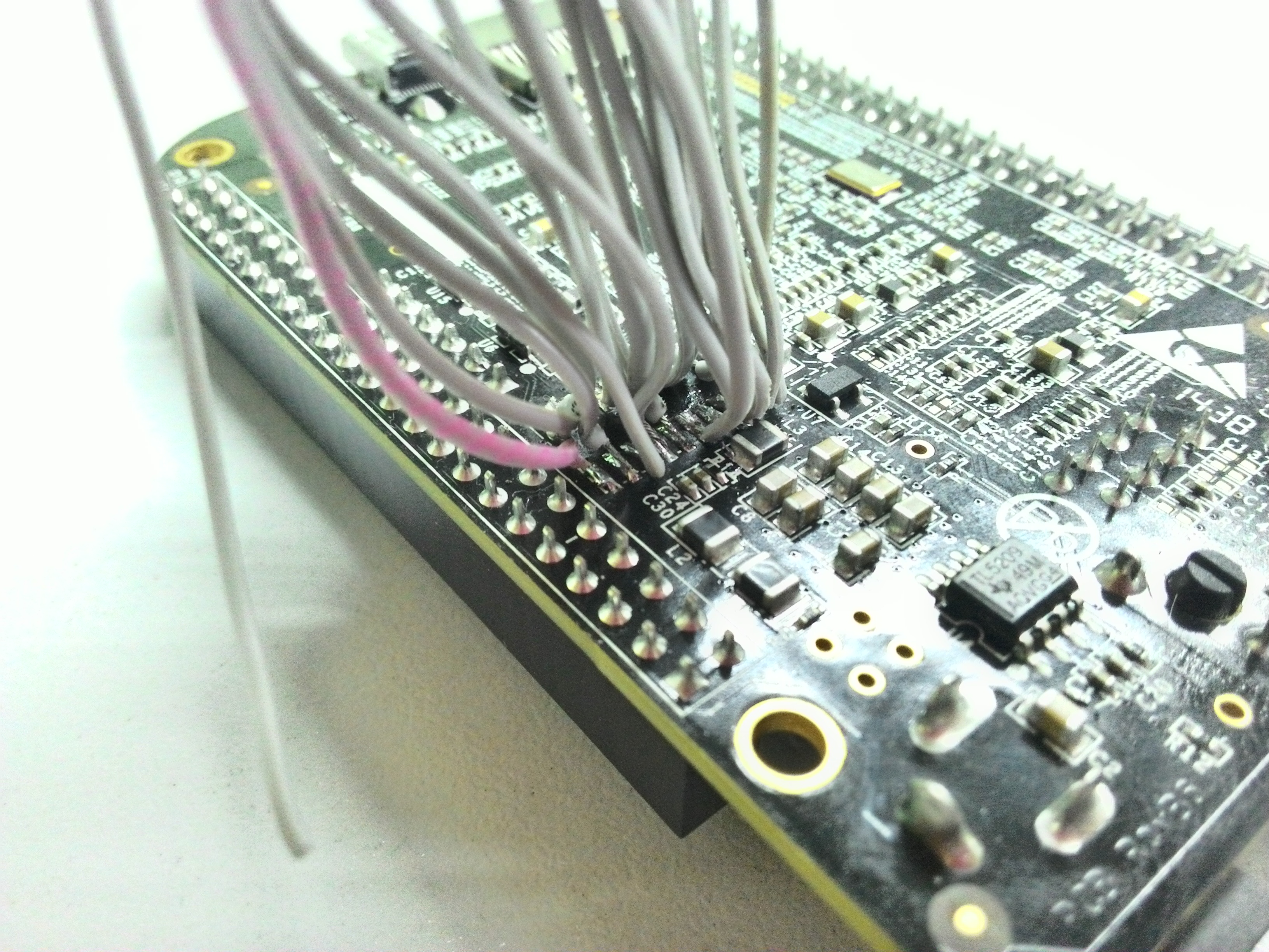
I use XDS100v2 20-pin TI connected with my board (beaglebone black), without JTAG header. I soldered 20-pin cable directly to the board and connected to XDS.
It looks like this:
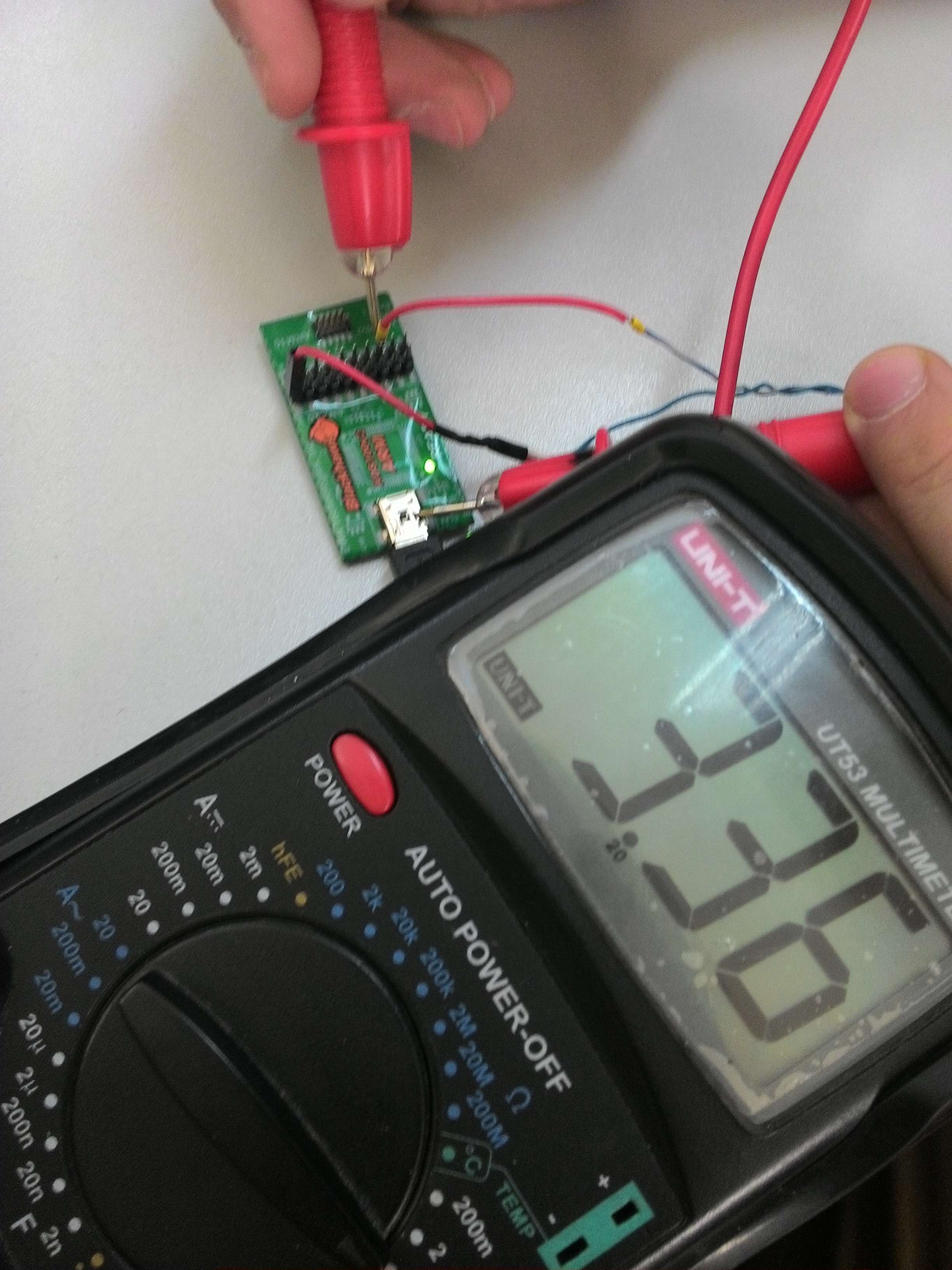
When I start "Test connection" in "Target Configuration", i get an error: 'SC_ERR_CTL_NO_TRG_POWER'
I checked each pin and on 5-th pin 3.48V. Or, i can't connected JTAG like that?
Best regards,
Svyatoslav
Svyatoslav,
I agree with Gautam: check for an open circuit or even shorts between pin 5 (TVRef) and other pins or pads on the board.
I also agree with Gautam regarding the use of a connector: the XDS100 will run its TCLK at 1MHz and the entangled wires may introduce a lot of crosstalk, inconsistent delays and there is a strong chance the JTAG communications will be degraded.
All in all, good luck with your connections.
Regards,
Rafael
Hello,
I believe that P2 on the BeagleBoneBlack is a compact TI 20-pin JTAG connection. You need to verify that you are translating the signals to an ARM 20-pin JTAG connection properly. This includes knowing which pin is Pin 1 on the USB100v2-ARM (XDS) unit. I mention this because in the image above with the volt meter it looks as if you are measuring voltage on Pin 3 (nTRST) with the other wire connected to pin 19.
As mentioned above, the wires can add a lot of noise and it may be better to solder a cTI header to the board and use the USB100v2 model that has a cTI JTAG connection.
BTW, you can refer to this TI document for JTAG headers and signal information: SPRU655
Cheers,
Andrew
Thanks, Ferrari.
I already ordered the header FTR-110-03-GD-06. I hope it will come as soon as possible.