


Part Number: LAUNCHXL-CC2640R2
Tool/software: Code Composer Studio
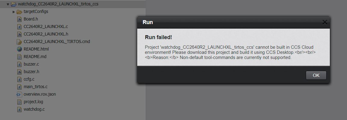
I have taken one of the TI Driver examples (watchdog) and attempted to modify to include some code to drive a tone buzzer. I thought I had this resolved, but I now get a new error. Note using CCS Desktop is a NON STARTER. I want to find an easy solution for CCS Cloud. I do not understand what "default tool-commands" the message is referring to.
I am using the following code which I found within another project (buzzer.c and buzzer.h). The only line of code I amended was in buzzer.c where I changed the timer reference library
#include <ti/devices/cc26x0/driverlib/timer.h>
/** ============================================================================
 *  @file       buzzer.c
 *
 *  @brief      PWM-based buzzer interface.
 *  ============================================================================
 */

/* -----------------------------------------------------------------------------
*  Includes
* ------------------------------------------------------------------------------
*/

// TI RTOS drivers
#include <ti/drivers/Power.h>
#include <ti/drivers/power/PowerCC26XX.h>

// Temporary PWM solution directly on DriverLib
// (until a Timer RTOS driver is in place)
#include <ti/drivers/pin/PINCC26XX.h>
#include <ti/devices/cc26x0/driverlib/timer.h>

#include "buzzer.h"


/* -----------------------------------------------------------------------------
*  Local variables
* ------------------------------------------------------------------------------
*/
static PIN_Handle hPin = NULL;

/* -----------------------------------------------------------------------------
*  Public Functions
* ------------------------------------------------------------------------------
*/

/*******************************************************************************
 * @fn          buzzerOpen
 *
 * @brief       Initialize the Buzzer
 *
 * @descr       Initializes pin and PWM
 *
 * @return      -
 */
void buzzerOpen(PIN_Handle hGpioPin)
{
    hPin = hGpioPin;

    // Turn on PERIPH power domain and clock for GPT0 and GPIO
    Power_setDependency(PowerCC26XX_PERIPH_GPT0);
    Power_setConstraint(PowerCC26XX_SB_DISALLOW);

    // Assign GPT0
    TimerConfigure(GPT0_BASE, TIMER_CFG_SPLIT_PAIR | TIMER_CFG_A_PWM);

    // Configure pin for PWM output
    PINCC26XX_setMux(hPin, Board_BUZZER, IOC_PORT_MCU_PORT_EVENT0);
}


/*******************************************************************************
 * @fn          buzzerSetFrequency
 *
 * @brief       Set the frequency (3Hz - 8 KHz)
 *
 * @return      return true if the requency is within range
 */
bool buzzerSetFrequency(uint16_t freq)
{
    uint32_t ticks;
    uint32_t loadLow;
    uint32_t loadHigh;
    uint32_t matchLow;
    uint32_t matchHigh;

    if (freq < BUZZER_FREQ_MIN && freq > BUZZER_FREQ_MAX)
    {
        return false;
    }

    // Stop timer during reconfiguration
    TimerDisable(GPT0_BASE, TIMER_A);

    // Calculate timer load and match values
    ticks = 48000000 / freq;
    loadLow = ticks & 0x0000FFFF;
    loadHigh = (ticks & 0x00FF0000) >> 16;
    matchLow = (ticks / 2) & 0x0000FFFF;
    matchHigh = ((ticks / 2) & 0x00FF0000) >> 16;

    // Set timer load
    TimerLoadSet(GPT0_BASE, TIMER_A, loadLow);
    TimerPrescaleSet(GPT0_BASE, TIMER_A, loadHigh);

    // Set timer match
    TimerMatchSet(GPT0_BASE, TIMER_BOTH, matchLow);
    TimerPrescaleMatchSet(GPT0_BASE, TIMER_A, matchHigh);

    // Start timer
    TimerEnable(GPT0_BASE, TIMER_A);

    return true;
}

/*******************************************************************************
 * @fn          buzzerClose
 *
 * @brief       Closes the buzzer interface
 *
 * @return      -
 */
void buzzerClose()
{
    // Configure pin as GPIO
    PINCC26XX_setMux(hPin, Board_BUZZER, IOC_PORT_GPIO);

    // Turn off PERIPH power domain and clock for GPT0
    Power_releaseDependency(PowerCC26XX_PERIPH_GPT0);
    Power_releaseConstraint(PowerCC26XX_SB_DISALLOW);
}
Buzzer.h:
/** ============================================================================
* @file buzzer.h
*
* @brief PWM-based buzzer interface.
*
* ============================================================================
*/
#ifndef _BUZZER_H_
#define _BUZZER_H_
/* -----------------------------------------------------------------------------
* Includes
* ------------------------------------------------------------------------------
*/
#include "Board.h"
/* -----------------------------------------------------------------------------
* Constants
* ------------------------------------------------------------------------------
*/
#define BUZZER_FREQ_MIN 3
#define BUZZER_FREQ_MAX 8000
/* -----------------------------------------------------------------------------
* Functions
* ------------------------------------------------------------------------------
*/
void buzzerOpen(PIN_Handle hPinGpio);
bool buzzerSetFrequency(uint16_t frequency);
void buzzerClose(void);
#endif
My main project file watchdog.c was amended as follows:
/*
* ======== watchdog.c ========
*/
#include <unistd.h>
#include <stdbool.h>
#include <stdint.h>
#include <stddef.h>
/* TI-RTOS Header files */
#include <ti/drivers/PIN.h>
#include <ti/drivers/Watchdog.h>
/* Example/Board Header files */
#include "Board.h"
/* new buzzer implementation */
#include "buzzer.h"
/* buzzer frequency for this application */
#define BUZZER_FREQUENCY 1000
/* Global memory storage for a PIN_Config table */
static PIN_State ledPinState;
static PIN_State buttonPinState;
//static PIN_State buzzerPinState;
/* Pin driver handles */
static PIN_Handle ledPinHandle;
static PIN_Handle buttonPinHandle;
static PIN_Handle buzzerPinHandle;
/*
* Application LED pin configuration table:
* - Board_PIN_LED0 is initially off.
*/
PIN_Config ledPinTable[] = {
Board_PIN_LED0 | PIN_GPIO_OUTPUT_EN | PIN_GPIO_LOW | PIN_PUSHPULL | PIN_DRVSTR_MAX,
PIN_TERMINATE
};
/*
* Application button pin configuration table:
*/
PIN_Config buttonPinTable[] = {
Board_PIN_BUTTON0 | PIN_INPUT_EN | PIN_PULLUP | PIN_IRQ_POSEDGE,
PIN_TERMINATE
};
/*
* Application buzzer pin configuration table:
* - Board_PIN_BUZZER is initially off.
*/
PIN_Config buzzerPinTable[] = {
Board_PIN_BUZZER | PIN_GPIO_OUTPUT_EN | PIN_GPIO_LOW | PIN_PUSHPULL | PIN_DRVSTR_MAX,
PIN_TERMINATE
};
bool serviceFlag = true;
bool watchdogExpired = false;
Watchdog_Handle watchdogHandle;
/*
* ======== watchdogCallback ========
* Watchdog interrupt callback function.
*/
void watchdogCallback(uintptr_t unused)
{
/* Clear watchdog interrupt flag */
Watchdog_clear(watchdogHandle);
watchdogExpired = true;
/* Insert timeout handling code here. */
}
/*
* ======== pinButtonFxn ========
* Callback function for the GPIO interrupt on Board_PIN_BUTTON0.
*/
void pinButtonFxn(PIN_Handle handle, PIN_Id pinId)
{
/* Clear serviceFlag to stop continuously servicing the watchdog */
serviceFlag = false;
}
/*
* ======== main ========
*/
void *mainThread(void *arg0)
{
Watchdog_Params params;
/* Call board init functions */
Watchdog_init();
/* Open LED pin */
ledPinHandle = PIN_open(&ledPinState, ledPinTable);
if(!ledPinHandle) {
/* Error initializing board LED pin */
while (1);
}
/* Turn OFF user LED */
PIN_setOutputValue(ledPinHandle, Board_PIN_LED0, 0);
/* Setup callback for button pin */
buttonPinHandle = PIN_open(&buttonPinState, buttonPinTable);
if(!buttonPinHandle) {
/* Error initializing button pins */
while (1);
}
if (PIN_registerIntCb(buttonPinHandle, &pinButtonFxn) != 0) {
/* Error registering button callback function */
while (1);
}
PIN_setInterrupt(buttonPinHandle, Board_PIN_BUTTON0|PIN_IRQ_POSEDGE);
/* Create and enable a Watchdog with resets disabled */
Watchdog_Params_init(¶ms);
params.callbackFxn = (Watchdog_Callback)watchdogCallback;
params.resetMode = Watchdog_RESET_OFF;
watchdogHandle = Watchdog_open(Board_WATCHDOG0, ¶ms);
if (watchdogHandle == NULL) {
/* Error opening Watchdog */
while (1);
}
/* Enter continous loop */
while (true) {
/* Service watchdog if serviceFlag is true */
if (serviceFlag) {
Watchdog_clear(watchdogHandle);
}
/* If watchdog expired since last started, turn ON LED */
if (watchdogExpired) {
PIN_setOutputValue(ledPinHandle, Board_PIN_LED0, 1);
// Turn on sound
buzzerOpen(buttonPinHandle);
buzzerSetFrequency(BUZZER_FREQUENCY);
sleep(5);
Watchdog_clear(watchdogHandle);
serviceFlag = true;
watchdogExpired = false;
PIN_setOutputValue(ledPinHandle, Board_PIN_LED0, 0);
// Turn off sound
buzzerClose();
}
}
}
I then added the following to my local Board.h file:
#define Board_GPIO_BUZZER CC2640R2_LAUNCHXL_GPIO_BUZZER
#define Board_PIN_BUZZER CC2640R2_LAUNCHXL_PIN_BUZZER
/* Buzzer */
#define CC2640R2_LAUNCHXL_PIN_BUZZER            IOID_15
/*!
* @def CC2640R2_LAUNCHXL_GPIOName
* @brief Enum of GPIO names
*/
typedef enum CC2640R2_LAUNCHXL_GPIOName {
CC2640R2_LAUNCHXL_GPIO_S1 = 0,
CC2640R2_LAUNCHXL_GPIO_S2,
CC2640R2_LAUNCHXL_GPIO_BUZZER,
CC2640R2_LAUNCHXL_GPIO_LED_GREEN,
CC2640R2_LAUNCHXL_GPIO_LED_RED,
CC2640R2_LAUNCHXL_GPIO_SPI_FLASH_CS,
CC2640R2_LAUNCHXL_GPIOCOUNT
} CC2640R2_LAUNCHXL_GPIOName;
GPIO_PinConfig gpioPinConfigs[] = {
    /* Input pins */
    GPIOCC26XX_DIO_13 | GPIO_CFG_IN_PU | GPIO_CFG_IN_INT_RISING,  /* Button 0 */
    GPIOCC26XX_DIO_14 | GPIO_CFG_IN_PU | GPIO_CFG_IN_INT_RISING,  /* Button 1 */

    /* Output pins */
    GPIOCC26XX_DIO_15 | GPIO_CFG_OUT_STD | GPIO_CFG_OUT_STR_HIGH | GPIO_CFG_OUT_LOW,  /* Tone Buzzer */
    GPIOCC26XX_DIO_07 | GPIO_CFG_OUT_STD | GPIO_CFG_OUT_STR_HIGH | GPIO_CFG_OUT_LOW,  /* Green LED */
    GPIOCC26XX_DIO_06 | GPIO_CFG_OUT_STD | GPIO_CFG_OUT_STR_HIGH | GPIO_CFG_OUT_LOW,  /* Red LED */


    /* SPI Flash CSN */
    GPIOCC26XX_DIO_20 | GPIO_CFG_OUT_STD | GPIO_CFG_OUT_STR_HIGH | GPIO_CFG_OUT_HIGH,
};

const PIN_Config BoardGpioInitTable[] = {

    CC2640R2_LAUNCHXL_PIN_BUZZER    | PIN_GPIO_OUTPUT_EN | PIN_GPIO_LOW | PIN_PUSHPULL | PIN_DRVSTR_MAX,       /* New Buzzer output definition */
    CC2640R2_LAUNCHXL_PIN_RLED      | PIN_GPIO_OUTPUT_EN | PIN_GPIO_LOW | PIN_PUSHPULL | PIN_DRVSTR_MAX,       /* LED initially off */
    CC2640R2_LAUNCHXL_PIN_GLED      | PIN_GPIO_OUTPUT_EN | PIN_GPIO_LOW | PIN_PUSHPULL | PIN_DRVSTR_MAX,       /* LED initially off */
    CC2640R2_LAUNCHXL_PIN_BTN1      | PIN_INPUT_EN | PIN_PULLUP | PIN_IRQ_BOTHEDGES | PIN_HYSTERESIS,          /* Button is active low */
    CC2640R2_LAUNCHXL_PIN_BTN2      | PIN_INPUT_EN | PIN_PULLUP | PIN_IRQ_BOTHEDGES | PIN_HYSTERESIS,          /* Button is active low */
    CC2640R2_LAUNCHXL_SPI_FLASH_CS  | PIN_GPIO_OUTPUT_EN | PIN_GPIO_HIGH | PIN_PUSHPULL | PIN_DRVSTR_MIN,  /* External flash chip select */
    CC2640R2_LAUNCHXL_UART_RX       | PIN_INPUT_EN | PIN_PULLDOWN,                                              /* UART RX via debugger back channel */
    CC2640R2_LAUNCHXL_UART_TX       | PIN_GPIO_OUTPUT_EN | PIN_GPIO_HIGH | PIN_PUSHPULL,                        /* UART TX via debugger back channel */
    CC2640R2_LAUNCHXL_SPI0_MOSI     | PIN_INPUT_EN | PIN_PULLDOWN,                                            /* SPI master out - slave in */
    CC2640R2_LAUNCHXL_SPI0_MISO     | PIN_INPUT_EN | PIN_PULLDOWN,                                            /* SPI master in - slave out */
    CC2640R2_LAUNCHXL_SPI0_CLK      | PIN_INPUT_EN | PIN_PULLDOWN,                                             /* SPI clock */

    PIN_TERMINATE
};

