This thread has been locked.

If you have a related question, please click the "Ask a related question" button in the top right corner. The newly created question will be automatically linked to this question.

DLP5530PGUQ1EVM: Unable to output image

Part Number: DLP5530PGUQ1EVM
Other Parts Discussed in Thread: LM25141

Hello!

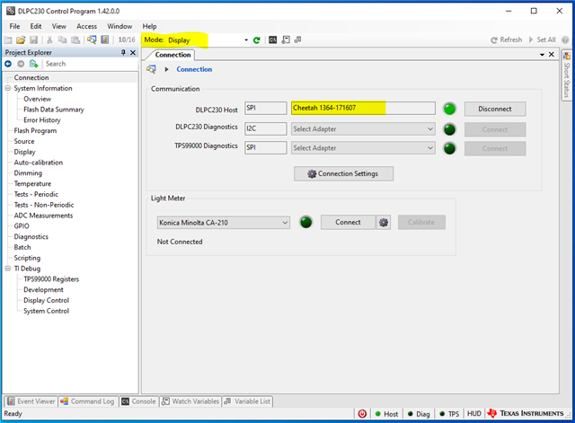
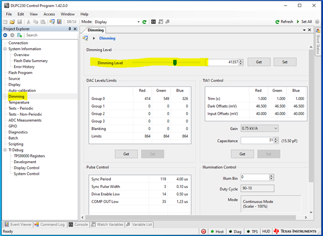
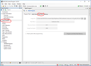
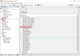
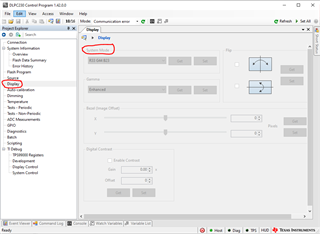
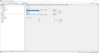
The device is powered by a 12V stabilized power supply, the D4 and D5 lights of the evaluation board are normally on, the control software on the computer can communicate, but there is no image light output, RGB-LEDs are also not lit, and the current value displayed by the power supply is small(about 0.1A). Can you provide a solution or debugging method, or provide an initial startup file for initialization?

Thanks for your help!

Tian

  • Hi Tian,

    Thank you for reaching out. 

    Would you happen to know what version of DLPC230 Control Program you have?

    In the following screen have you made sure the Mode is set to "Display" and it shows the Cheetah is connected? If the Mode is in "Standby" or "Calibration" then there will be no output from the EVM. 

    If you look at the lens of the EVM do you see any light coming out of the EVM? Sometimes the brightness may be set very low but the EVM is still on and fully functioning. You can check the brightness by going to the Dimming tab and moving the slider or manually inputting a value up to 65535. 

    Please let me know if you have any other questions and hope this helps. 

    Thanks,

    Alex Chan

  • Hello, Chan!

    Thank you for your reply!

    I understand the current situation of the DLPC230 control software, it is indeed set to DIsplay mode, and the Dimming level has been set to the maximum value, but still no light output is observed. However, no errors were reported in the communication of the software. I intercepted other pages in the software. Only some errors were displayed in ADC Measurements. Do you think this is the cause of the problem? Do you think the current problem is in hardware or software? How to solve this?

    Thank you again for your help!

    Tian

  • Hi Tian,

    Could you try reading the flash and then emailing it or attaching it for me so I can try on another EVM in the lab? My email is a-chan@ti.com

    Additionally have you tried going to the Sources tab and trying different test outputs. Are there any errors? You can also look into the lens and see if the DMD mirror positions are changing. You can use a flashlight to better see if there is a reflection of light as the DMD mirrors move. 

    Could you also try changing the system modes and see if you get any errors or if that changes anything?

    Thank you for your time and hopefully we can find a solution to get this resolved. 

    Thanks,

    Alex Chan

  • Hi Chan,

    Thank you for your suggestion. I have read out the flash and sent it to your email address later. Thanks.

    I tried other output options in the Sources tab, but none of the light output was observed. However, your suggestion about observing the DMD through the lens is very effective. I observed that the DMD mirror is obviously different under the on and off conditions. As shown in the picture, you can see obvious stripes. Regarding the display mode, I tried other modes, but there was also no output. I found that the software you use here is not the same as the one I downloaded from the official website. Does this have any effect?

    Please contact me if you find any problems.

    Thanks for your help!

    Tian

  • Hi Fangxu Tian,

    Sorry for the delay there was a July 4th Holiday so many people on the team were out. 

    I flashed the flash data you had sent me onto a known working EVM in the lab and everything works fine so I do not believe it is the flash issue or controller issue. Talking with a few people on my team, we believe it may be an issue with the driver board. 

    I had asked one of the system engineers and he recommended the following checks on the driver board. 

    • Measure Pre-regulator output voltage on pin 2 of H2.  Depending on jumper position voltage will be either 6.5V or 8.1V.
    • Check for signals on the following testpoints:
      • TP8 – Red enable
      • TP7 – Green enable
      • TP5 – Blue enable
      • TP6 – Shunt enable
      • TP4 – DRVEN
      • TP3 – SYNC
    • Check for activity on gate and drain of Q4

    Let me know if you have any questions and thank you for your patience. 

    Thanks,

    Alex Chan 

  • Hello, Chan,

    Sincerely thank you for your help and suggestions.

    I also think it should be a problem with the driver board. I checked the positions you listed.

    The voltages of TP8 to TP3 are 1.74V, 2.32V, 1.24V, 1.21V, 3V, 0.08V, respectively. H2 means that the two pins on the side marked 8V are connected, but the detected voltage is only about 2mV. The detection of the 4 pins on the same side of Q4 is also only 2-7mV.

    I think it may be that the driver board is not supplying power to the LEDs. What do you think is the specific fault? Is it possible that the electronic components or chips on the driver board are damaged?

    Thanks!

    Tian

  • Hello!

    Do you have any new discoveries or conclusions? 

    So is it caused by damage to the electronic components on the drive board, or is it due to other reasons?

    If there is any new information, please reply as soon as possible.

    Thanks!

    Tian

  • Hi,

    Sorry for the delayed response. Could you please check the Vin signal to the LM25141 Buck Converter which is U2 on the controller board. Additionally just wanted to double check the H2 header is in the correct installation across pins 2 and 3 as indicated in the red box. 

    Thank you for your time. 

    Thanks,

    Alex Chan