This thread has been locked.

If you have a related question, please click the "Ask a related question" button in the top right corner. The newly created question will be automatically linked to this question.

DLPNIRSCANEVM: TIVA software compiling - map LEDs to expansion connector J3

Part Number: DLPNIRSCANEVM

Hi all,

I am a new user of DLP NIRScan Nano. I want to map LEDs to the expansion connector J3, and I found the following tutorial:

e2e.ti.com/.../faq-dlp-light-control---dlp-nirscan-and-nirscan-nano-faqs

I followed the instruction at the bottom, and after trying different versions of CCS I finally managed to recompile the TIVA firmware and map the LEDs to the expansion connector pin 5 (SCAN, YELLOW, PA4) and pin 6 (POWER, GREEN, PA5). The LEDs ground ports are connected to pin 9. 

Pin 6 works as is should, namely the LED is flashing as it did on the TIVA board. However, pin 5 (SCAN) works inversely: the LED (3.3V signal) is ON all the time, but switches OFF during the SCAN. This is the exact opposite as it used to work on the TIVA board, where LED turns ON during the scan, and is OFF otherwise.

Is there a way to correct this issue with the SCAN LED, to make it ON only during the SCAN also on the expansion connector?

Many thanks and kind regards

ps.: I just noticed that when the board goes to hibernation, the GREEN LED (POWER) stops flashing and instead is ON all the time (not OFF as it used to be on the TIVA board when in hibernation). Is there a way to correct this? 

  • Andrew,

    Welcome to the E2E forums and thanks for your interest in our DLP technology.

    It sounds like the signals you are driving are behaving differently than intended, but still working. Have you tried checking the nirScan Nano reference design schematic to check how these signals are actually being driven on the EVM? You can compare this against the pinout connections you are using in your updated setup and see if you need to modify the code that drives the GPIO pins.

    Find the schematics here: https://www.ti.com/tool/TIDA-00554

    Best Regards,

    Philippe

  • Philippe, 

    many thanks for your reply.

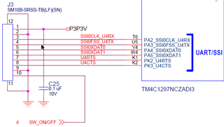
    As far as I understand the schematics (and I am a total noob here), signals are driven to the J3 expansion connector via Tiva TM4C1297NCZADI3 microcontroller, through the UART/SSI stage. See the attached image:

    The ports and the pinout connections that I am using is correctly defined throughout the code (for example in common.h), namely PA4 and PA5 are pin 5 and pin 6, respectively. And they work, I get the signal, but the only problem is that it is inverted, namely the YELLOW_LED_EXP_CONN // PA4 signal is ON when it should be OFF, and vice versa. I also suspect the same is happening with GREEN_LED_EXP_CONN // PA5, since it remains ON when in hibernation. But when the GREEN LED is flashing, in looks normal, just like it used to flash on the TIVA BOARD.

    I scrolled through the gpio.c and uart.c files in the driverlib, but I have no idea how to interpret stuff in there. Another simple solution would be to make a simple NOT gate with a transistor, to invert the signal. But if this can be solved in the TIVA software, it would be better.

    Best regards

  • Andrew,

    I just looked at the TIVA driver libraries and they seem to have full support for configurations of the GPIO directions and levels. You should be able to leverage the functions provided in those libraries to get the effect you want.

    If you want to understand the code better, I recommend using search tools that let you scan the entire code database and trace where these functions are used to better understand how they should be implemented.

    Best Regards,
    Philippe

  • Thanks Philippe.

    Any suggestions on what I should search in particular? I searched for gpio*, uart* and ssi* keywords throughout the entire code, but have not found anything that would ring a bell, i.e., signal levels and/or signal switches. But as I mentioned, I am not very experienced in this kind of coding, so any suggestions are welcome.

    Best wishes

  • Andy,

    I see a repository with GPIO TIVAware code here. You can see the GPIO write function within: https://github.com/yuvadm/tiva-c/blob/master/driverlib/gpio.c 

    Let me know if you want to get into specifics.

    Regards,

    Philippe

  • Dear Philippe,

    many thanks for your patience and willingness to help.

    I checked the gpio.c, and I think that the solution could be to modify the code either at line 572, to set the pad configuration for specific pins, or at line 2382, where GPIOPinTypeLEDSeq procedure starts, where I also found this comment:

    // Set the pad(s) for push/pull operation and 8mA strength. The external
    // hardware should be set up such that we sink current when the LED is
    // turned on, hence the 8mA configuration choice.

    Nevertheless, I have no idea how to do it. So either some of you experts provide the specific solution, or I will simply implement a logic NOT gate before LED and solve the problem hardware-wise. 

    Best wishes

  • Andrew,

    I think you should look at the GPIOPinWrite function on line 1038. That is probably what you are looking for.

    If you are not as comfortable with modifying and rebuilding the software, however, I don't think there would be a problem with simply using a hardware gate to fix the problem. This would certainly reduce the complexity of your solution.

    Let us know if you have further questions.

    Regards,

    Philippe