This thread has been locked.

If you have a related question, please click the "Ask a related question" button in the top right corner. The newly created question will be automatically linked to this question.

DLP3010EVM-LC: How to remove high-frequency flickering (1-2kHz) when displaying at 120*3=360fps mode on DLP3010EVM-LC

Part Number: DLP3010EVM-LC
Other Parts Discussed in Thread: DLP3010, DLPC3478

Dear TI,

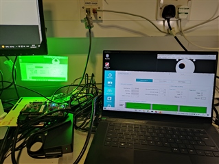
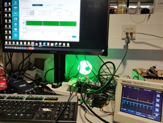
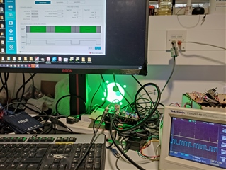
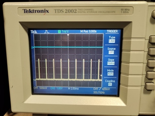
The DLP3010EVM-LC has high frequency flickering (1-2kHz) when displaying at 120*3=360fps mode.

the parameters I set via the GUI system ("light control" tab) are:

Frame Rate = 120.9044

Illumination = G

Bit Depth = 8

Pre-exposure Dark Time (us) = 171

Exposure Time (us) = 2555

Post-exposure Dark Time (us) = 31

Is there anything I can do to remove the high-frequency flickering, and only display 360fps video?

Cheers.

Best,

Jiaqi Huang

  • A video clip is attached here, hope it's helpful... 

    https://youtu.be/V4DtRrpSyWA

    JH

  • Jiaqi,

    From the above it appears you have configured an exposure time of a bit under 2500 us for your green segment. Is that correct?

    Since you only have one color in this case, it would be expected that you will see dark time during the rest of the frame period (which is around 5500 us of time). Do you have a photodetector available to verify your light output against your sequence pattern configuration?

    Regards,

    Philippe

  • Dear Philippe,

    The exposure time was set to 2555 (us), as described before.

    The problem is the flicker (i.e. the whole screen was set full-bright for a brief moment repeatedly. as was shown in the attached youtube video). Some dark frames were preprogrammed to be there. 

    I am expecting to see only the video (i.e. the rotating disk, with four dots at the corner, and some dark frames), without flicker (i.e. a frequent brief full-bright screen, which eliminates the frame contrast).

    What is the cause of the DLP3010 flicker? how can I eliminate that flicker? 

    Cheers.

    JH

  • Hi Jiaqi,

    In the video you shared shot at 2200 fps I saw the flicker every 6 frames. which is ~360 fps.

    have you tried longer and shorter exposure times? do you still see this flicker?

    Regards,

    Arthur

  • Dear Arthur,

    Thanks for pointing out, yes, it's a 6-frame interval between two adjacent full-bright frames. the flicker is around 360fps indeed.

    I am trying the shorter exposure period, but the system mentioned that the minimum exposure time is 2555 us. So I tried 2560, 2565, 2570, 2575 (us) to make sure the 360 fps is still possible (pre-Dark=171us, post-Dark = 31us), but no difference. The projected screen is still green, at the pixels where it should be black (I guess that's indicating the 360Hz flicker, Sorry, I don't have access to the 2200fps camera today, from my 240Hz mobile phone camera video shot, I can see flicker).

    Does that mean the 360Hz full-bright screen is interpolated by the DLP system when it receives a new 120Hz-frame from the HDMI input?

    Cheers.

    All the best,

    JH

  • Hi Jiaqi,

    In your case with 8 bit depth pattern the minimum exposure time is 2555 us.

    please see the light control sequence timing information here https://e2e.ti.com/support/dlp-products-group/dlp/f/dlp-products-forum/778576/faq-sequence-timings-for-dlpc347x-light-control-platform?tisearch=e2e-sitesearch&keymatch=faq%3Atrue

    since your pattern seems binary, only black/white, can you try using 1 bit depth pattern? from the sequence timing info a 2555 us exposure time will put you in the middle of the exposure time range, rather than at the very minimum for 8 bit depth.

    Regards,

    Arthur 

  • Hi Arthur.

    How do I stream a 1-bit (depth) video via the HDMI cable to the DLP?

    Or shall I just switch to 1-bit on the DLP GUI, and the DLP will automatically pick up the last bit of each pixel from the 8-bit video stream.

    I've just tried the 1-bit (exposure = 800 us) settings via the GUI. Looks like the 360Hz flicker is gone (at least on my 240Hz phone camera).

    I'll need to verify the performance with the 2200 fps camera one day I have access to it.

    Thanks very much.

    JH

  • Jiaqi,

    there is no considerations needed from the HDMI source side. If you set 1-bit (depth) in the GUI the DLPC will only project the first bit of video data.

    The DLPC3478 datasheet has explanations of exactly which bits are being projected in 1 and 8 bit modes.

    Regards,

    Arthur

  • Dear Arthur,

    I've tried renewing the video format to suit the 1-bit mono mode (3 patterns per frame). And capturing the video with a 2200fps camera.

    Found out the DLP3010 is not splitting the 3 patterns in a frame, instead, it's shown three frames together 3 times.

    youtube video: https://www.youtube.com/watch?v=FnLAWB3th_M

    in the video, the last digit of the frame number is overlapped from 3 patterns.

    Is there anything I can do about it? 

    Cheers.

    JH

    (N.B.: parameters: exposure = 1700us, pre-dark = post-dark = 500us)

  • Jiaqi,

    Thanks for trying this. We should be able to respond to you early next week with feedback of our own.

    Regards,

    Philippe

  • Thanks very much, Philippe.

    Looking forward to having the new feedback.

    Cheers.

    JH

  • Jiaqi,

    It doesn't look like the team has had a chance to address this yet due to backlog. I apologize for the inconvenience.

    We will try to address your question within the next couple of days.

    Regards,

    Philippe

  • Thanks, Philippe. 

    Sure. please let me know if you'd like to have the AVI file which I used to test the DLP3010. (or the Python [openCV] code which generates the AVI video.)

    Cheers.

    JH

  • Jiaqi,

    If you are comfortable sharing it, any additional collateral is always helpful for us to better understand the problem. Please share if you can.

    Regards,

    Philippe

  • Hi Philippe,

    The Python (OpenCV) code for generating the video can be found here: 

    https://github.com/Blueasteroid/Project_DLP/blob/master/JH_gen_DLP3010_stim_RotCav_for_Texas_Instruments.py

    Please have a try. If not working properly, I can send the video to you too.

    (The video itself is quite big in size. if you'd like to have it, please provide me an email address. I can send the file over via a file exchange server.)

    Cheers.

    JH

  • Jiaqi,

    Thanks. We will take a look at the same and let you know.

    Regards,

    Philippe

  • Jiaqi,

    What is the firmware version you are using to test out the external pattern display functionality. Can you probe the Trig_Out1 and Trig_Out2 signals and verify if they are getting configured properly based on the exposure time settings. 

    Regards,

    Mayank 

  • Mayank,

    The firmware version is 7.3.2.

    I am also using Teensy LC to send I2C bytes to the DLP3010, according to document: dlpu075a.pdf ... e.g.

        byte comm[] = {0x96,0x00,0x03,0x02,0x07,0x07,0,0,0xF4,0x01,0,0,0xF4,0x01,0,0};  // dlpu075a.pdf - 3.4.7

    How can I access Trig_out1 and Trig_out2? (Is there any document about this diagnosis? is there any risk of damaging the device?)

    what is the proper shape of the signal?

    what can I do about the DLP3010, if the trigger signal is good or bad?

    Cheers.

    JH

  • Jiaqi,

    You should be able to use a standard oscilloscope to probe the trigger out signals. Do you have a particular concern?

    Regards,

    Philippe

  • Dear Philippe,

    I couldn't find the "Trig_out1" and "Trig_out2" labels in the document: tidrcg7a.pdf, nor on the product PCB.

    I just want more information, and hopefully, only an essential test to run. (it has been 21 days, and there seem still endless un-conclusive tests to run...)

    It would be a great help to have a document, e.g. a bullet point-based instruction with photos and labels, to save our time and avoid the endless mutual questioning.

    Hope it makes sense, Thanks very much.

    JH

  • Jiaqi,

    Let me elaborate in hopes of helping explain the above more clearly:

    There are two signals TRIG_OUT_1 and TRIG_OUT_2 as described in the DLPC3478 datasheet: https://www.ti.com/lit/ds/symlink/dlpc3478.pdf

    If you go to Table 7-3 you will see that these two signals are sourced from TSTPT_4 and GPIO_07 respectively. These signals are both labelled as such in the schematic for this EVM: https://www.ti.com/tool/TIDA-080003 

    Using pads attached to these signals, you can measure TRIG_OUT_1 and TRIG_OUT_2 per the instructions Mayank provided in a post earlier and print the results to an oscilloscope. At the moment, we suspect that the pattern configuration you are using is not being properly reflected in the actual system. Based on these trigger output signals, you should be able to determine the real behavior of the system and adjust your GUI configuration accordingly. 

    I hope this helps.
    Regards,

    Philippe

  • Philippe,

    Thanks for the detailed instructions.

    I've tried 8-bit and 1-bit mode, neither of them has Trig_out signals output (only 0V signals).

    I've also probed pin-8 on J4 (POWER_TP_SEN), by curiosity, which is also 0V. 

    Tracing back, there is no jumper on J11 (3-pin connector) on the mainboard of DLP3010. 

    My question is:

    1. Is this POWER_TP_SEN the power of the trig_out signals?

     2. if so, which voltage should I use for powering the trig_out signal? the P3P3V_SB or P1P8V on J11?

    Please advice.

    Thanks very much.

    JH

  • JH,

    You are correct that this is the reference voltage for the trigger signals.

    The intention is to select the reference which matches up with whatever device you are triggering onto. Of course, in this case you could pick either one. You should be able to see the trigger signal once you attach it.

    Regards,

    Philippe

  • Dear Philippe,

    Thanks for the confirmation of the power-related question.

    I've got the photos for both the 8-bit mode...

    and 1-bit mode:

    To my point of view, the 8-bit mode has the correct trig_out signals.

    But the 1-bit mode does not. 

    (for the 1-bit mode, I can see the trig_out1 is 60 Hz, not 104.2 Hz, according to the manual. And there are 5 Trig_out2 pulses, instead of 3.)

    On my AMD RX550 video card settings, the output frame rate of ITE6801 is always 120 Hz.)

    Please let me know if there are any parameters/settings I should take care of...

    Thanks very much.

    (it's 7 pm here at GMT+0 zone, I'll reply on Monday. Cheers.)

    JH

  • JH,

    Thanks for the feedback. It sounds like there may be a problem either with the video source or the pattern configuration. If you haven't already, please share your 1-bit pattern configuration so that the team can try to reproduce the problem and provide a solution.

    Regards,

    Philippe

  • Dear Philippe,

    Thanks for the reply.

    The parameters for the 1-bit pattern configuration should be: 

    exposure = 1799 us, pre-dark = 500 us, post-dark = 500 us

    (for reference, it is also listed in the second picture above, visible after zoom in.)

    Please let me know if you need more information.

    Cheers.

    JH

  • Hello JH,

    Team will get back to you in couple of days.

    regards,

    Vivek

  • Hello JH,

    I have send you a friend request on the e2e forum. We will try to debug this issue together via private messages. 

    Regards,

    Mayank

  • Hi Mayank,

    FYI, the friend request has been accepted.

    Cheers.

    JH

  • JH,

    Thanks for the reply. If you have any difficulty accessing private message conversations let us know.

    Regards,

    Philippe

  • Hi Philippe,

    Thanks for providing more support. 

    At the moment, there is no message notification in my TI account.

    I haven't used the TI online system too much, don't know where I should click to get the message (I assume top right corner).

    Maybe a "hello world" message from the team would help me allocate the message notification.

    Thanks very much!

    Best,

    JH

  • JH,

    There is a message icon on the top right corner section. Also, you will get an email notification when somebody sends out a message to you. I will reach out to you via PM before end of this week.

    Regards,

    Mayank

  • Hi guys,

    Are there any updates regarding the "8bit mode flickering" and "1bit mode incorrect pattern interpolation"?

    I've done more tests with a photodiode and collected some data in the figures, shown below.

    Note: in the 8bit mode, there are 360Hz white screen flashes at "black screen". in the 1bit mode, the frame should be split into 3 patterns, not 5.

    The pictures were the signals from a photodiode, which is placed in front of the DLP3010.

    Looking forward to the solution (for displaying a 360Hz video stream from a 120Hz HDMI source, without any unwanted flashes).

    Cheers.

    Jiaqi Huang

  • Hello JH,

    Thank you for your patience. This week is  holiday week in US and our responses are slow.  We will get back to oyu early next week.

    regards,

    Vivek

  • Hello Jiaqi Huang, 

    Apologies for the late response. Can you please update the firmware to the latest release (available here - https://www.ti.com/tool/DLP3010EVM-LC) and let us know if you still see the same 1bit pattern display inconsistency as reported earlier.

    Thanks and regards,

    Mayank

  • Dear Mayank,

    Thanks for the advice.

    That link doesn't work properly. but I've downloaded and upgraded the firmware to 8.0.0 from the TI product page.

    The result is still the same.

    But I had done a bit more analysis based on the photodiode signal.

    Looks like the output pattern rate at 1-bit mode is what I want (around 360Hz, yellow curve), same as the setting (120Hz, 3 patterns per frame). 

    Could it be that the problem of the 5-pattern burst might be related to the video source, I assume?

    As I remember in the manual, the 1-bit mode requires 104.2 Hz video input.

    My video card was set to output two duplicated screens at 120Hz.  (video card: Nvidia RTX 3070)

    But the photodiode measured a 60 Hz interval between two adjacent "5-pattern" bursts (or between two rising edges of the chunk of the square waves in the yellow curve).

    My question would be:

    1. why 104.2 Hz, how to get a 104.2 Hz HDMI video source? (what device was used in TI?)

    2. if 104.2 Hz is not necessary, is there a way for the DLP3010 to adapt to 120 Hz HDMI input?

    Thanks.

    BTW, the 8-bit mode still has a 360 Hz flicker at the "black screen". No difference from the previous firmware.

    Cheers.

    Jiaqi Huang

  • Sorry for too many words above, simply speaking, how to remove the dip in the yellow curve, make it either 360Hz or 0 Hz.

    Cheers.

    Jiaqi Huang

  • Hi Jiaqi,

    We will need some more time to look into this. Thank you for your patience. 

    Thanks

    Chris

  • Jiaqi, 

    We use video generators like ASTRO to send external sources via HDMI. The timing of the external sources is configurable using such video generators.

     I will try to checkout the 8bit mode pattern display at 360hz to see if we can reproduce the flicker problem. I will get back to you by Wednesday. 

    Regards,

    Mayank

  • Hi Jiaqi Huang,

    Sorry for the delayed response. 

    We were able to test with 8-bit external pattern mode by using video generator ASTRO to send external source via HDMI at 3*120Hz. However, I couldn't reproduce the issue by using the same dark time and exposure time settings with white screen. I also don't see unexpected light output by using Black screen as input image. 

    Can you please also try to test with a black screen to see if there is any unexpected light output?

    I suspect there may be a problem with your video source.

    Thanks,

    Lori 

  • Hi Lori,

    I've tried again, the result is the same, still has 360Hz flickers.

    Figure (left) 360Hz pulses from the photodiode. (middle) the arrangement of the DLP, photodiode, and a "BLACK" screen (full screen of a black bitmap image, looks green because of the 360Hz flicker at 8-bit Green channel mode.). (right) data of the photodiode from a black screen to a non-black screen.

    The video card we use is an Nvidia RTX3070 in a newly purchased gaming computer (with a decent 750W power supply).

    (So far, we tried video cards from Radeon RX550, RTX3070 (laptop), and RTX3070 (desktop), all with the same result.)

    We don't have ASTRO here.

    How about finding an HDMI from an Nvidia card on your side? showing a black screen through HDMI, to see if the problem can be replicated.

    Cheers.

    JH

  • Hi JH,

    Thank you for providing the information!

    I'll need to contact the team if we can find the same configuration as yours.

    Regards,

    Lori 

  • Thanks, Lori.

    I would guess any Nvidia card can be a good starting point.

    Cheers.

    JH

  • Hi JH,

    Unfortunately, we don't have video card to reproduce your issue. ASTRO is our lab equipment to generate and test the video source. 

    It's hard for us to debug the issue since we couldn't reproduce it. It mostly seems like the issue is not related to the EVM, so I would recommend you to check your video card if it has the correct image.

    Regards,

    Lori

  • Dear all,

    I bumped into a previous post on TI, describing the input/output difference on ITE6801: https://e2e.ti.com/support/dlp-products-group/dlp/f/dlp-products-forum/595782/dlp3010-different-data-between-input-and-output-of-ite6801

    Is there any solution for that?

    And how may I access the PDATA pins on the DLP3010 on my side, to make sure the ITE6801 output is correct? 

    Thanks very much.

    JH 

  • Hi JH,

    Please see the design files for this EVM here: https://www.ti.com/tool/TIDA-080003#design-products. You will need to trace or extract contact points for probing the PDATA lines on the controller side.

    Thank you,

    Chris

  • Thanks, Chris, for the datasheet.

    Instead of soldering 24 cables to the PDATA pins, I used 1-bit mode to output 23 bits pattern (not 24 bits) of a white screen, and the photodiode gets...

    As the image shows, the HDMI signal should be 0xFF = 255 (white screen), but the photodiode gets 11010111 = 0xD7 = 215.

    And the photodiode gets one pulse in each pattern on a black screen, where the HDMI signal should be 0x00 (not 0x01 or 0x80).

    (The HDMI input was set to 60Hz during the test, I am hoping to get a 180Hz output from the DLP.)

    The previous post (Link) showed something similar, where the input and output of the ITE6801 were different.

    I suspect, there is something wrong with the ITE6801 output during the black screen, which causes the 360Hz flashes described previously.

    May I ask what was the signal train look like, when using the HDMI signal from ASTRO?

    And if the ITE6801 has a problem, is there any way to fix the ITE6801?

    Thanks very much.

    JH

  • Hi JH,

    A few questions:

    1. Can you share what the HDMI input is to the ITE card ?
    2. Can you confirm if your video generator is outputting the correct video data ?
    3. Do the ITE6801 specs meet the requirements for your application ?

    If the ITE6801 has an issue you will need to contact the manufacturer of the chip.

    Thanks

    Chris

  • Hi Chris,

    Thanks for the reply, and the suggestions for the new test protocols.

    We were trying to split out the HDMI signal and record the HDMI signal with a 1 G Sample/second oscilloscope. But was not successful. 

    Every time we connected the TMDS data2+/- (pin 1 & 3) of the HDMI to the oscilloscope, the DLP3010 was blacked out.

    Not sure if it is because of the HDCP protection.

    Are there any recommendations for monitoring/recording the HDMI signal, which will be sent into the ITE6801 chip?

    (Would there be an alternative chip to replace ITE6801 on the DLP3010?... just for curiosity.

    I've asked the ITE company, but no reply yet.)

    Thanks.

    JH

  • Hello JH,

    There are not test points between the HDMI port and the ITE6801 or tools that we can provide to monitor the activity through the interface. Wiring out the connection pins on the HDMI port may allow you to see the electrical signal activity at the port while wiring RA1, RA2, and RA3 will allow you to see the signals downstream from the ITE. However, it will likely be difficult to make sense of this data.

    There is no alternative currently for the ITE6801.

    Have you had any success in lowering the resolution or data rate being fed into the HDMI interface? Did this change the behavior at all?

    Regards,

    Austin