This thread has been locked.

If you have a related question, please click the "Ask a related question" button in the top right corner. The newly created question will be automatically linked to this question.

DLP5530PGUQ1EVM: cannot activate 'Display' mode

Part Number: DLP5530PGUQ1EVM

Dear TI Team,

A while ago, I purchased a DLP5530PGUQ1EVM. Unfortunately, I can't get an image on my screen when projecting, so I wanted to ask you for help.
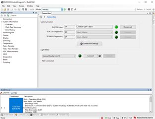
Every time I try to use the projector in "Display Mode" or "Calibration Mode", I get an error message. ( Image 1 )
Also, I can't insert a picture via the "Flash Program" menu to reset the flash memory, because I don't have the possibility to save one in *.img or *.bin format. Third party files from the internet don't work either.
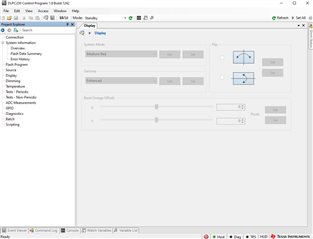
As a result, most of the functions are greyed out and therefore unusable. ( Image 2 )

Do you have an alternative or a solution for this?
I would be grateful about a positive feedback!

With kind regards,

David Mueller


  • Hi David,

    Our DLP5530PGUQ1EVM expert has been notified of this support request.

  • Hello David -

    For me to help debug, could you please send me more details about the pre-loaded firmware? To do so, you can take a screenshot of the System Information > Overview" page (after clicking on the "Get" button).

    Thanks and regards,

    Ross

  • Hi,

    This will be a response to the following e2e chain as well.

    https://e2e.ti.com/support/dlp-products-group/dlp/f/dlp-products-forum/1072858/dlp5530pguq1evm-reply-to-dlp5530pguq1evm-cannot-activate-display-mode

    The main issue customer was seeing was a red LED D6 was on which is a sign of a bad connection when the EVM was powered up. Additionally they had some connection issues that was due to wrong cable placement. The solution to these issues will be discussed below.

    Cable Connection Setup

    Please follow the connection steps and ensure cables are connected correctly.

    a. Ensure the LED cables are correct and take note of the specified color specific connectors.

    b. Ensure Formatter controller to Driver Control Flex Cable connection is correct.

    c. Ensure other cables are connected properly

    • Attach the HDMI cable to the computer and other end to micro HDMI port (J3)
    • Connect Cheetah cable to the computer and connect adapter from Cheetah box to the cable already connected to SPI port (J2)
    • Connect the power cable to (J1) and connect plugs to Power Supply set to 12V.
    • Power up the Power Supply (Ensure there are no current limiting features on the power supply)
    • Power on the DLP EVM using SW4.

    DMD Interface Issue:

    Sometimes the DMD may not be seated properly in the Controller board interface.

    Look sideways at the EVM and in between the optical engine and the bottom controller board and you should see two rectangles. The black rectangle is the adapter on the controller board while the light gray rectangle is the DMD itself. Make sure it is flush fit on all sides. If you see any pins showing or a gap, that can lead to the red LED D6 turning on and communication issues when trying to connect with DLPC230 Control Program.


    You will need to follow these steps to partially disassemble the EVM. 

    a. Unplug all cables and safely power off any power supply or connections.

    b. If your EVM has a heatsink make sure to remove it.

    c. Remove the bottom screws and make sure to hold onto the screws and don't lose them.

    d. Now you can check the DMD fit to the socket interface on the controller board. Press down firmly and uniformly onto the DMD sides and do not touch the center array of mirrors. You should hear a click and visually inspect all sides to ensure secure fit. If the DMD needs to be completely removed there are small indents on the sides where a small flathead screwdriver can be used to gently pry off the DMD.

    e. For reassembly make sure you screw back on the Controller Board with even screw pressure. Do not tighten one screw and then the other as this can cause the DMD to get tilted out of the socket interface again, gradually tighten both screws evenly. Check to make sure the DMD has not tilted afterwards by checking all sides of the interface.

  • Thank you very much to Ross and Alex who helped us figure the DMD connection issue out via video call!

    I also want to stress the very last part again: be VERY careful to really "gradually tighten both screws evenly"! After the call yesterday, I wanted to put the heatsink back on again and promptly managed to create another gap between the DMD and the adapter :D