This thread has been locked.

If you have a related question, please click the "Ask a related question" button in the top right corner. The newly created question will be automatically linked to this question.

DLP5530Q1EVM: modifying EVM as per user requirement

Part Number: DLP5530Q1EVM
Other Parts Discussed in Thread: DLPC230-Q1

sir i am new to DLP5530Q1EVM and just to perform outbox testing as per the instruction given in user guide i started it and it worked successfully for me but now i have some doubts which i have mentioned below and all these are with respect to video projection

1  how to set input video resolution its given in user guide "input video resolutions are programmed in the Extended Display Identification Data (EDID) EEPROM" so my doubt is how to program this EEPROM because the given supported resolution in user guide are not available on standard windows laptop  ?

2 everything is controlled using DLPC230-Q1 Control Program Lite GUI so how to program this EVM from scratch as per our application requirement ?

3 how to get Image File (.bin) (default)  so as to Reprogram the Onboard Flash Memory ?

4 is there any lecture or training available so as to learn more about this EVM 

  • Hello -

    The most helpful information about this EVM can be found in the User's Guide document. Can you please explain what you are hoping to do with the EVM, and we can provide dedicated instructions.

    1) The EDID that comes pre-programmed will tell the graphics card on a standard windows laptop to output the expected resolutions of 1152x576. Have you tested this yet?

    2) What are your application requirements, and how do they differ to what comes programmed by standard?

    Regards,

    Ross

  • sir i am trying to use DLP5530Q1EVM  as plug and play module but every time i have to follow up the steps given in user guide to project my desktop display on DLP5530Q1EVM 

  • Hello Vinay -

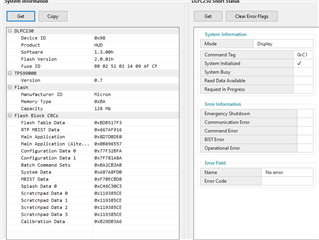
    I can provide a new flash binary that defaults to HDMI 1152x576 input. But first, can you please take a screenshot of the "System Information > Overview" page in the DLPC230 Control Program? Be sure to press the "Get" button.

    Thanks,

    Ross

  • i will soon share you the screenshot but i have some doubt regarding the dlp composer software we want to create our own custom GUI to control the EVM so i want to know what's the process of programming the EEPROM of dlpc230-q1 without dlp composer

    i have read some application notes where a method of scripting was used so how to modify or write our own binary script to control the evm as per our own requirement and how to burn the script on EVM without DLP COMPOSER software 

  • Hello Vinay -

    Are you talking about the DLPC230 EEPROM or SPI Flash?

    The protocol for the host commands of the DLPC230 can be found in the Programmer's Guide, which includes programming the DLPC230 flash. Are you familiar with this document?

    Can you elaborate more on your second point? On which device will you burn the script on the EVM? The only programming that the DLP5530Q1EVM supports is for the DLPC230 SPI Flash. The firmware binary file itself must be generated via DLP Composer, and the programming of this binary must be done via the Control Program GUI or through your custom host command interface.

    Regards,

    Ross

  •  

    actually my problem is i want to control DLP5530Q1EVM using external interface

    suppose i want to flip an image on DLP5530Q1EVM  using a push button at my hmi panel I am sensing that button using a microcontroller now i want to send a command to DLP5530Q1EVM to flip the image once button is pressed now my problem is how to setup either I2C or SPI and how to send command to dmd over this ?

  • Hi Vinay -

    In that case, my proposal would be implement the SPI (or I2C) command protocol (according to DLPC230 Programmer's Guide) inside your Host MCU in order to send the 'flip' commands whenever it senses the button press.

    Regards,

    Ross

  •  sir i want your help in setting up SPI communication with  DLP5530Q1EVM I have 2 options as follows

    1st as you suggested using a host MCU in our case its an FPGA board which is a later stage task in our project since we are not at all familiar with SPI usage of  DLP5530Q1EVM

    so we are using  2nd option i.e  to use cheetah SPI adaptor supplied with the  DLP5530Q1EVM I want to know is there any other software or interface other than DLPC230-Q1 Control Program Lite GUI where I can send directly commands given in DLPC230-Q1 programmers guide to DLP5530Q1EVM using SPI interface and if its so then what the format of sending the commands and how to setup clock and other related signal.

    please if possible can you  give an example of command structure for flipping image to be send by host SPI cheetah adaptor 

  • Hello Vinay -

    The DLPC230-Q1 Control Program Lite GUI is the only software tool that is readily available to send commands to the DLPC230-Q1. Unfortunately we do not have an SDK available at this time.

    If you are unable to make use of the Control Program GUI, then you will need to implement your own SPI / I2C protocol. The format of sending the commands (including setting up the clock and other related signals) can be found in Section 3 of the DLPC230-Q1 Programmer's Guide for Display Applications. Details of the Image Flip command can be found in section 5.1.6.

    This document should serve as a sufficient resource to implement the host communication protocol. Of course, if you have specific questions about the implementation or need help debugging, we are happy to help.

    Regards,

    Ross

  • thank you so much for your response support given by you  will help me a lot in setting up the SPI protocol .

    last thing i want to know role of CHEETAH SPI ADAPTOR can't I  directly use 5 wire (CLK,MISO,MOSI,SCL,GND) from host MCU to communicate to DLP5530Q1EVM rather than using CHEETAH SPI ADAPTOR

  • Hi Vinay -

    The purpose of the Cheetah SPI is to convert a USB signal to SPI. It allows users to control the EVM with a PC (via USB cable).

    For a host MCU where you have control of the 5 wires, you can program it to speak directly to the DLPC230-Q1 without the need for an intermediate adapter like the Cheetah.

    Regards,

    Ross

  • does the pre loaded binary files in DLP5530Q1EVM let automatically spi to happen i.e once i send the command using opcode given in programmers guide the command will be executed in real time unlike scripting  in DLPC230-Q1 Control Program Lite GUI where i have to run(compile) the script eveytime  ,or i have to change binary files data 

  • Hi Vinay -

    No need to change the binaries or any configuration. The EVM comes pre-configured for SPI communication. As long as you wait for the system to initialize (refer to Figure 4.1 in the programmer's guide - though this process is < 1 second), it will be ready to receive commands in real-time. No need to compile like needed for the GUI python scripting.

    Regards,

    Ross

  • thank you so much

  • sir i tried a setup where i used Arduino to setup SPI since i have very little knowledge about spi i am finding it difficult to send  command over that SPI could give an example of simple command to be sent to perform any task so that we could take that as reference and perform other task also 

  • sir i tried a setup where i used Arduino to setup SPI since i have very little knowledge about spi i am finding it difficult to send  command over that SPI could give an example of simple command to be sent to perform any task so that we could take that as reference and perform other task also 

  • Hi Vinay - 

    Here is some sample code that was developed in python which sends an SPI command to the DLPC230. Note this should be used as a reference only.

    import serbus, time
    from crcmod import Crc
    import pullup_control
    from pullup_control import *
    
    
    crcobj = Crc(poly=0x107, initCrc=0xFF, rev=False, xorOut=0, initialize=True)
    spibus = serbus.SPIDev(1)
    cs = 0
    i2cbus = serbus.I2CDev(2)
    i2cAddr = 0x1B
    
    
    def calc_crc(bytes):
        crc = crcobj.new()
        crc.update(buffer(bytes))
        return crc.crcValue
    
    def i2c_status():
    
        i2c_message = bytearray([0xC0, 0x01, 0x00])
        crcResult = calc_crc(i2c_message)
        i2c_message.append(crcResult)
    
        print("The HIB sent:")
        for byte in i2c_message:
            print hex(byte)
        
        i2cbus.open()
    
        value = list()
        i2cbus.write(i2cAddr, list(i2c_message))
        time.sleep(0.01)
        value = i2cbus.read(i2cAddr, 8)
        print("The DVH responded:")
        for byte in value:
            print hex(byte)
        print value
        print type(value)
    
        i2cbus.close()
    
    def spi_status():
        spi_message = bytearray([0xC0, 0x01, 0x00])
        crcResult = calc_crc(spi_message)
        spi_message.append(crcResult)
    
        #insert dummy bytes
        for x in range(0,5):
            spi_message.append(0x00)
        print("The HIB sent")
        for byte in spi_message:
            print hex(byte)
        
        spibus.open()
        spibus.setMaxFrequency(cs, 10000000)
        spibus.setBitsPerWord(cs,8)
        spibus.setClockMode(cs,0)
        spibus.setCSActiveLow(cs)
        spibus.setMSBFirst(cs)
    
        response = spibus.transfer(cs, list(spi_message))
        print("The system responded:")
        for byte in response:
            print hex(byte)
        spibus.setCSActiveHigh(cs)    
        spibus.close()
    
    def run_demo():
        pullup_control.initialize()
        sleep(0.05)
        pullup_control.poweron()
        sleep(1)
        spi_status()
    
        sleep(3)
    
        pullup_control.poweroff()
    
        sleep(5)
    
        pullup_control.setpin(HOST_IF_SEL, 1) #I2C Host interace
    
        pullup_control.poweron()
    
        sleep(3)
    
        i2c_status()
    
        pullup_control.poweroff()
    
       # sleep(2)
    
    run_demo()


    Regards,

    Ross