Because of the holidays, TI E2E™ design support forum responses will be delayed from Dec. 25 through Jan. 2. Thank you for your patience.

This thread has been locked.

If you have a related question, please click the "Ask a related question" button in the top right corner. The newly created question will be automatically linked to this question.

Controller/DMD incompatible

Part Number: DLPLCR67EVM
Other Parts Discussed in Thread: DLPC900

Hello,

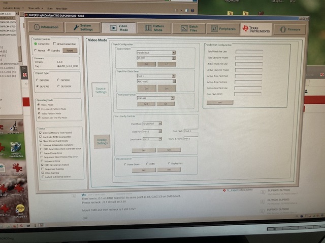
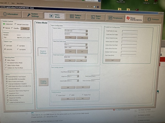
I'm trying to have my DMD work out of the box. I have a DLPLCR67EVM connected to a DLPLCR9000DEVM. When I power the board, the LEDs D5, D11 and D12 light up, and D7 and D9 blink. I then connect the board via USB to my computer. In the DLP LightCrafter DLPC 9000 GUI 5.0.0, the DMD is said to be connected. Firmware version appears to be 6.0.0. However, one of the status is "Controller/DMD incompatible", and I can't change the Operating mode to anything else than "Video Mode".

I tried "updating" the firmware, by uploading *.img files. I then get a first message: "Bootloader needs update: Existing on HW - v0.0.0 New - 3.1.0. Select YES to update bootloader.” Whether I press Yes or No, a second message pops up: “Unable to read flash device IDs. Error: Invalid command number: 0x15”, and the D9 LED goes off.

The flex cables are almost not bent. We use the recommended power supply. We have never moved/touched the board when it was powered on. We have this problem since we tried using the DMD for the 1st time. Do you have any advice on how to solve the problem? And, more specifically, is it possible to output a log that tells us if the DMD is recognized/correctly connected?

Thanks,

Gabriel

  • Gabriel,

    Sorry you are having issues.  Please try a different USB cable and reload the firmware.  

    Please use the BOOThold Jumper - J12.  The procedure can be found on page 57 of the current Dual DLPC900 EVM guide [DLPU102A]. 

    I also recommend deleting the FlashLoaderCache directory, if it exists, in the location of the firmware you are attempting to load.

    If that does not work, let us know.

    Fizix

  • Gabriel, 

    There are also UART headers that can be connected to get output to a terminal emulator.  Please see page 62 of the EVM guide.

    Fizix

  • Hi Fizix,

    I used a different USB cable and it didn't change anything.

    I used the BOOThold Jumper J12, and installed the Master and Slave *img files, installation worked but after powering down,  removing the BOOThold Jumper and powering up again, I still had the same issue: status shows "Controller/DMD incompatible". I didn't see any FlashLoaderCache directory.

  • Hi Gabriel,

    Thanks for updating the firmware and sharing results.

    I hope the Flex cable is connected in proper direction (DMD End to DMD board) and screws are tight. 

    Can you please take snap shot of GUI, EVM board and share it.

    Capturing UART debug log will provide with additional details to debug the problem.

    Thanks,
    Shivakumar

  • Hello,

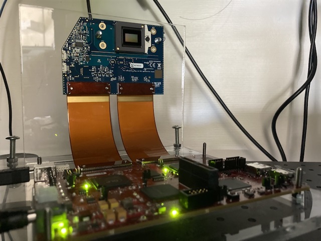
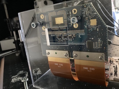
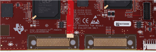
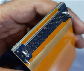
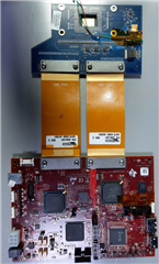
    I think the screws on the flex cables are tight -- I did not force excessively on them though. Here are snapshots of the board and the cables.

    board

    DMD with flex cables

    And here is what the GUI looks like when the board is connected.

    GUI when 1st connection

    Then I click "Reset", and the GUI looks like this:

    GUI after reset

  • Hello Gabriel,

    I can confirm for Shiva from the pictures that the flex cables are correctly oriented. 

    I would first recommend getting the serial port connected (primary controller first) and get the output and letting Shiva look at the results.

    You may then want to carefully remove the flex cable ends that are connected to the controller board and check for any debris on the pads or the pins.  If that does not solve it then try the DMD board connectors. 

    Although I doubt this is the issue, it is worth a look.  You can use IPA to carefully clean the pads.  The pins on the cable I would use a small brush, but not a cloth or wipe since it tends to snag fibers and add more debris.

    Last, lay the DMD board so the DMD is face up and carefully turn the ZIF cam screw about 180 degrees.  Then gently turn it back.  This is in case any of the pins did not make good contact.

    Fizix

  • Hi Gabriel,

    Thanks for sharing the images.

    Before doing the experiment Fizix suggested, please correct the Flex cable connection.

    I suspect flex cable connected to controller board is not in correct direction.

    The conductive pins in the controller board is at the top layer. 

    But looking at the images you have shared, Flex cable pins are not touching the pins of the controller board.

    Flex cable pins should be touching the pins exposed on the controller board.

    Sharing photo from the development hardware available with me. After making proper flex cable connection, final arrangement should look like this.
      

    Please correct the flex cable connection and update the result.

    Thanks,
    Shivakumar

  • Gabriel,

    Shiva is correct.  I was looking to see if the ends that say DMD were connected to the DMD board correctly.  I missed that they are on the wrong side of the controller board. This should fix the issue.

    Fizix

  • Thanks a lot, I’ll try that tomorrow and will let you know

  • Thank you Gabriel.

    Regards,

    Matt

  • thanks a lot, it looks like it's working -- I don't have the "Controller/DMD incompatble" anymore, and can change the operating mode to "Pattern on the fly". One last question: to power off the controller, is there an On/Off button or should we just disconnect the power adapter?

  • Fantastic Gabriel! 

    Thank you for letting us know and I will mark this as closed.

    Fizix

  • Hi Gabriel,

    Great to know that issue is resolved now.

    It will be good to move the system to standby state first and then disconnect the power.
    This way, controller can park the DMD mirrors and prepare the system for power down.