This thread has been locked.

If you have a related question, please click the "Ask a related question" button in the top right corner. The newly created question will be automatically linked to this question.

DLP3030Q1EVM: what program do I need to burn when I just want to light up the PGU?

Part Number: DLP3030Q1EVM

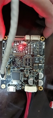
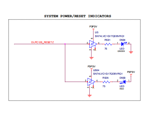
We have received a dlp3030q1evm circuit board making document and schematic diagram document, version D. I want to know whether it is normal to turn on the red light before burning the software? If normal, what program do I need to burn when I just want to light up the PGU?

  • If the situation is wrong, how can I solve this problem?

  • How do I connect this circuit board when I burn the program?

  • The following is the schematic file.

    7028.2514132E_dlpc120_formatter.pdf

    The following is the BOM file.There are some electronic materials that we think can be replaced, which have been marked in yellow.

  • Is it OK to only connect the power input connector and SPI communicator connector when burning the program?How do we burn? Is there a corresponding demonstration video? If there is no demo video, you can give me the file which I can program circuit board(DLP3030Q1EVM).

  • Hi Mr. Wang,

    You should not be seeing a red light, are you able to connect to the DLPC120 control program and do you see any error messages or what does the System Information section say?

    In terms of how to flash the system please see the following user guide under section 5 and use the following attached configuration file. You should be able to flash the system as you have it set up assuming you are able to get a green LED and connect correctly.

    DLPU059_ACP_UsersGuide_March2018 (2).pdf

    CFG_EVM_RevC_2C653471_20180111_COR_MP_v3.zip

    As for the component replacements, please give me some more time to look over that.

    Thanks,

    Alex Chan

  • Hi Alex Chan,

    I can connect to the DLPC120 control program.However, I don't feel like a normal connection.

    After connecting,It shows SPI Flash Mode.And some menu options are not available.Is this normal?

    The following menu options are not available.

    Program Piccolo SW(Cheetah SPI)

    Program Calibration Data(Cheetah SPI)

    RGB27 Calibration

    System Control:

                  Dimming Control

                  Display Mode and Command Lists

                  Temperature Compensation

                   DMD and Heater Control

    However, the circuit board purchased directly from the official website shows this after connection.

    We can't buy some electronic materials, so we use replacement materials. Will this affect the normal function of the circuit board? I look forward to your reply on this question.The following is the diagram and table of the prototype number of the replaced electronic material and the replacement table of the model currently in use.

    仅替换的电子物料汇总.xlsx

    If it is convenient, please reply as soon as possible.

    Thanks,

    Mr. Wang

  • Hi,Alex Chan,

    In order to make it easier to demonstrate the problems we encountered, we made two videos.

    The two videos respectively demonstrate the status of the circuit board with problems and the circuit board purchased before connected to the software。

    The first video shows the status of the circuit board(DLP3030Q1EVM) we are now experiencing problems after connecting the DLPC120 Automotive Control Program 1.4.2.58 software and opening the software。

    The second video shows the state of the circuit board(DLP3030Q1EVM) we bought before in DLPC120 Automotive Control Program 1.4.2.58 software and after the software is turned on.

    Thanks,

    Mr. Wang

  • Hi Mr. Wang,

    It is advised to use a newer version of the DLPC120 Automotive Control Program such as version 2.0 or above. Do you have access to mysecure software to access the DLP Auto HUD Gen 1.5 Control Program download page?

    Thanks,

    Alex Chan

  • Hi,Alex Chan

    I use a newer version of the DLPC120 Automotive Control Program version 2.0 .0.0 today,but the problem still exists.I don't have access to mysecure software to access the DLP Auto HUD Gen 1.5 Control Program download page.Can you tell me how to download DLPC120 Control Program SW V2.1.2.0 and install this software?

    If I want to have access to mysecure software to access the DLP Auto HUD Gen 1.5 Control Program download page,what should I do?

    Thanks,

    Mr. Wang

  • Hi,Alex Chen

    SPI Flash Program(Cheetah SPI):What file should I choose here?Can you tell me the name of the file that needs to be selected? What should be the name of the file?What should be included in the file?Can you provide it?

    Thanks,

    Alex Chan

  • Hi Mr. Wang,

    Can you confirm that the system with problems did you modify or attempt to flash or program it in any way? 

    If you opened it straight from the box and plugged it into the computer and it was showing a red light that may be something wrong with the board itself.

    Thanks,

    Alex Chan

  • Hi,Alex Chen

    OK, I will check my circuit board itself. About installing the software, I follow the installation method in the following picture. Is this correct?

    To better illustrate the installation(DLPC120 Automotive Control Program version 2.0 .0.0) process, I recorded a video.

    I noticed that there are two memory type chips(TMS320F28023PTQ,IS25LP064A-JMLE) in this circuit board . Could you tell me about the working principles of these two memory type chips in this circuit board?

    After measurement, we found that the voltage(3P3V) was normal.Then the input(DLPC120_RESETZ) may be incorrect.How do I measure this input(DLPC120_RESETZ)?What should the correct input look like?If I know it,I think I can know why  one of the two LEDs are red.

    Thanks,

    Mr. Wang

  • Hi Alex Chan,

    I noticed that if I want this circuit board to work, this flash(IS25LP064A-JMLE) also needs to burn programs. Do you know what programs this flashIS25LP064A-JMLE) needs to burn?If you know ,please tell me.How do I burn this program?

  • Hi Alex Chan,

    I noticed that it was showing a red light that The circuit board is OK in this mode(SPI Flash Mode).

    Maybe there is something wrong with my operation.

    Thanks,

    Mr. Wang

  • Hi Mr. Wang,

    I have tried to create a video of the basic flashing routine where you would first flash the ASIC flash which is to the IS25LP064A-JMLE and then the calibration data is programmed to the onboard flash memory of the TMS320F28023PTQ. 

    The video can be found here:

    https://e2e.ti.com/support/dlp-products-group/dlp/f/dlp-products-forum/1082393/faq-dlpc120-q1-dlp-auto-hud-gen-1-5-resources

    I have also attached a demo folder of calibration data and configuration file. This calibration data was created from another system so it may not be optimized for your system but we can use it to test to see if we can get things working. 

    20220303_v2_example.zip

    Thanks,

    Alex Chan

  • Hi,Alex Chan

    I noticed that I need an xds100 V2 emulator (5.2). Can you recommend one for me? Maybe it is this wrong step (I may have used the wrong emulator) that caused the burning error.

    Thanks,

    Mr.Wang

  • Hi Mr. Wang,

    Let me double check this information from the documentation you had sent. Thank you for your patience.

    Thanks,

    Alex Chan

  • Hi Mr. Wang,

    The steps you sent a picture of only need to be done on a fresh PCB but any EVM that you buy from TI should already be flashed and the steps do not need to be performed.

    The name of the emulators are the ones you circled in blue. If you for example look up xds100 V2 emulator you will see various options for sale.

    Thanks,

    Alex Chan

  • Hi,Alex Chan,

    OK,I have bought an emulator(XDS100 V2).After performing step 5.2, the light turns green.This is exciting.

    I buy ten fresh PCB and some EVM that I buy from TI. So I should flash ten fresh PCB and the steps need to be performed.

    Thanks,

    Mr.Wang

  • Hi,Alex Chan,

    Thank you for your patience.But there are still some problems to be solved.Look at this file,One type(Cfg Data Identifier) is inconsistent with another(ASIC App Flash Data).Maybe there are some files we chose wrong.


    There are some documents we need. Can you provide them?

    First, what should I choose in this file(Piccolo Main Application(hex file))(5.3  Programming Piccolo Main Application)?

    Second,what should I choose in this file(Calibration File,Config File)(5.4  Programming Calibration and Configuration File)?


    Can you provide the above documents?

    The type(Cfg Data Identifier,ASIC App Flash Data) on our circuit board is 2C653471. The type(Cfg Data Identifier) you provided is 3DFDB5A3. Therefore, we hope you can provide files related to this type(2C653471).

    Thanks,

    Mr.Wang

  • Hi,Alex Chan,

    The following pictures show the problems we encountered.

    Thanks,

    Mr.Wang

  • Hi Mr. Wang,

    So for your first question regarding the Piccolo Main Application please see the attached file. In the picture it shows the exact file path for the piccolo main application hex file. 

    HUD_Piccolo_SW_Release_v0.21-74 (1).zip

    For your second question, did you see the video that I had sent previously in this message chain? In the above message I provided you a zip folder with the same files shown below. 

    There is a video that will first show you how to program the ASIC flash where you will use file #1 shown below. Then the video shows how to program the calibration data where you will use the same file #1 for the cfg file and then file #2 for the cal file. Please make sure you program the ASIC flash first and then the calibration data just like in the video. 

    Hope this helps.

    Thanks,

    Alex Chan

  • Hi,Alex Chan,

            Thanks for your patience.I have solved this problem.

    Thanks,

    Mr.Wang