This thread has been locked.

If you have a related question, please click the "Ask a related question" button in the top right corner. The newly created question will be automatically linked to this question.

DLPDLCR2000EVM: Black replaced with blue

Part Number: DLPDLCR2000EVM
Other Parts Discussed in Thread: DLP2000, DLPM2000EVM,

Hi

An issue has crept in with my DLP2000 and I'm wondering what it could be, I've had a similar issue but with a yellow tint on another model before. The device was working fine for a while but now exhibits this behaviour regardless of rewiring or setup. Is this a calibration issue or damage of some sort?

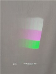
The splash screen displays well, however when using a test image I get the following:

(With this input image)

my /boot/config.txt is setup for a 480 x 480 output and has been working fine for a while until this issue started:

# Disable the optional hardware interfaces
dtparam=i2c_arm=off
dtparam=i2s=off
dtparam=spi=off

max_framebuffers=2

# Disable compensation for displays with overscan
disable_overscan=1

[cm4]
# Enable host mode on the 2711 built-in XHCI USB controller.
otg_mode=1

[all]
dtparam=audio=off

[pi4]
# Run as fast as firmware / board allows
arm_boost=1

[all]
# Add support for software i2c on gpio pins
dtoverlay=i2c-gpio,i2c_gpio_sda=23,i2c_gpio_scl=24,i2c_gpio_delay_us=2

# DPI Video Setup
dtoverlay=dpi18
overscan_left=0
overscan_right=0
overscan_top=0
overscan_bottom=0
framebuffer_width=480
framebuffer_height=480
enable_dpi_lcd=1
display_default_lcd=1
dpi_group=2
dpi_mode=87

dpi_output_format=458773
hdmi_timings=854 0 14 4 12 480 0 2 3 9 0 0 0 60 0 32000000 3

And my setup commands: 

sudo i2cset -y 11 0x1b 0x0c 0x00 0x00 0x00 0x13 i ;
sudo i2cset -y 11 0x1b 0x0b 0x00 0x00 0x00 0x00 i ;

sudo i2cset -y 11 0x1b 0x16 0x00 0x00 0x00 0x07 i

sudo i2cset -y 11 0x1b 0x12 0x0 0x0 0x0 0xC8 i ; 
sudo i2cset -y 11 0x1b 0x13 0x0 0x0 0x0 0xC8 i ; 
sudo i2cset -y 11 0x1b 0x14 0x0 0x0 0x0 0xC8 i ; 
sudo i2cset -y 11 0x1b 0x39 0x0 0x0 0x0 0x1 i ; 
sudo i2cset -y 11 0x1b 0x3a 0x0 0x0 0x0 0x1 i ; 
sudo i2cset -y 11 0x1b 0x38 0x0 0x0 0x0 0xd3 i ; 
sudo i2cset -y 11 0x1b 0x15 0x3a b ; 
sudo i2cset -y 11 0x1b 0x00 ; 

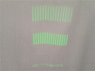
Finally when I turn off the blue LED using the i2c commands I get the following image:

  • Hello User,

    Welcome to the E2E forum and thank you for your interest in DLP technology!

    Can you say what changed before the apparent drop in blue data? Was the firmware re-flashed or did the board sustain damage?

    Can you comment on your intention behind the commands listed above? As I am looking them over, some of the data values that you have sent in are unexpected.

    Additionally, please try re-flashing the firmware image onto the EVM. It may be that there has been a corruption in the flash image.

    Regards,

    Austin

  • sudo i2cset -y 11 0x1b 0x0c 0x00 0x00 0x00 0x13 i ; (Set resolution)
    sudo i2cset -y 11 0x1b 0x0b 0x00 0x00 0x00 0x00 i ; (Set input to parallel)
    
    sudo i2cset -y 11 0x1b 0x16 0x00 0x00 0x00 0x07 i ; (Turn LED on)
    
    sudo i2cset -y 11 0x1b 0x12 0x0 0x0 0x0 0xC8 i ; (Set red brightness reg to 250)
    sudo i2cset -y 11 0x1b 0x13 0x0 0x0 0x0 0xC8 i ; (Set green brightness reg to 250)
    sudo i2cset -y 11 0x1b 0x14 0x0 0x0 0x0 0xC8 i ; (Set blue brightness reg to 250)
    sudo i2cset -y 11 0x1b 0x39 0x0 0x0 0x0 0x1 i ; (Set brightness commands)
    sudo i2cset -y 11 0x1b 0x3a 0x0 0x0 0x0 0x1 i ; (Set brightness commands)
    sudo i2cset -y 11 0x1b 0x38 0x0 0x0 0x0 0xd3 i ; (Set brightness commands)
    sudo i2cset -y 11 0x1b 0x15 0x3a b ; (Set brightness commands)
    sudo i2cset -y 11 0x1b 0x00 ; (Set brightness commands)

    Command intentions appended above

    I believe the only thing that changed between the issue starting was a power cycle, although there's a possibility this could have happened while I2C commands were executing if that is relevant and it may not have been a clean shutdown of the Raspberry Pi Zero 2W host device

    Thanks for the advice, I will attempt re flashing the firmware next

  • Thomas, 

    Yes, please try re-flashing the firmware and let us know your findings. 

    Regards,

    Mayank

  • Thanks, I have found the appropriate firmware .bin file, is there a guide to flash this from my Raspberry Pi host device using i2c commands?

    I have had a look at the DLP2607 Software Programmers Guide and believe I can use compound commands to do this, but I'm not 100% sure of every step regarding uploading/flashing the firmware.bin file itself.

    I understand there is a method using the Windows GUI application "Pico Loader" but this requires some USB to i2c hardware that I cant seem to easily source in the UK

  • Hello User,

    Yes, please see Section 2.3 of the DLPC2607 Software Programmer's Guide. In particular, sub-section 2.3.2.3.4 will be useful to you.

    What resolution are you looking to set with the following command?

    sudo i2cset -y 11 0x1b 0x0c 0x00 0x00 0x00 0x13 i ; (Set resolution)

    The value of 0x13 is not listed as a valid input resolution.

    Regards,

    Austin

  • Hi,
    Thanks for bringing this up, I was looking to use any resolution with a height of 480p (As I am using a 1:1 aspect ratio for my content anyway), and my boot/config.txt timings were setup for 854x480, which seems to correspond to value 0x19, however upon testing, only the value of 13 seems to work with my current /boot/config.txt, all other valid resolution values give a glitched/distorted display output. I will try some different timings and report back on this one

    I will attempt to write a small Python program to handle the flash upload this weekend and let you know how I get on

  • It seems no other combination of video timing and i2c resolution config settings I've tried play nicely with my setup, I'm not too sure why this could be with that one

    Regarding the flashing of the device, is there a considerable risk in using the low level i2c commands to rewrite flash on this unit? and is there any reference program or batch file for the process so I can be sure everything is correct prior to running my own?

    Would replacing the DLPM2000EVM head unit be a potential fix to the original black/blue issue?

  • Hello User,

    Please allow us some time to look into this behavior. We should have a response by next week.

    Thank you,

    John 

  • Hi Thomas,

    If the 0x13 value to 0x0C is not causing any obvious drop in performance, it is likely not an issue. If this value were incorrect the output would likely not appear as it does.

    I am reconsidering the reflash point since this may be a more difficult suggestion. Additionally, upon further reflection, corrupted flash data would result in more drastic image quality issues.

    How do the test patterns appear? In particular, I would be curious about the horizontal gray ramp with or without the other LED's disabled. If these appear with good quality we may have to consider the video data front end configuration.

    Swapping in a new optical engine may be indicative if you have one readily available. Otherwise, the LED's appear to be working well since we are seeing white output.

    Is this display being cut down? There appears to be a significant illuminated border around the color bars. Is this intentional?

    Regards,

    Austin 

  • Thanks for the suggestions, I will run the built in test patterns on Monday and get back to you with results (EDIT: Results now done below)

    Regarding the cut down display, this is intentional yep, this due to my target use case using 1:1 ratio (For this case 480 x 480) content at all times, partly to allow seamless rotation. This is done by forcing a 480 x 480 framebuffer as per the /boot/config.txt in the top post of the thread.

    In fact this is why the issue was more noticeable, previously the cut off area to the left and right of the image would be black as expected, so you got a perfectly square image (projection angle/surface allowing), as if the projector itself were perfectly 1:1, which was perfect. Since this issue started instead this area left and right of the image has become blue, and you can now clearly see the "true" aspect ratio of the projection with the blue bars.

    Edit: I accidentally marked my own reply as being useful to me due to using my touchscreen phone and so I deleted my original reply to undo this

  • All 13 test inputs appear perfectly when using a balanced (Eg 255, 255, 255) LED brightness settings, so it seems the issue is limited to the parallel video output mode.

  • Hello Thomas,

    The thread is still open, so there is not need for concern about marking the issue as resolved.

    Please let us know the results of the test pattern tests when available. If these are displaying well we should investigate the wiring between the EVM and Raspberry Pi.

    Regards,

    Austin

  • Thanks, the test patterns are indeed displaying well

    The wiring between the EVM and the Pi is a PCB module, gerbers available here: https://www.pcbway.com/project/shareproject/Pi_Zero_to_TI_Pico_Projector_Board.html

    The key connections of the PCB follow the wiring outlined here: http://frederickvandenbosch.be/?p=2948 using an 18-bit/RGB666 bus

    The PCB is soldered directly to the DLPDLCR2000EVM, with a Pi Zero 2W connected directly to this PCB via a pin header, as I say this wiring and software setup was previously fine and is quite securely mounted, and I've tried refitting the Pi and continuity testing the pins with a multimeter but I can't see any issues there yet

    I have tried some other i2c commands relating to the pixel data format and colour, and got some improved results

    If I try the command:

    "sudo i2cset -y 11 0x1b 0xC3 0x00 0x00 0x00 0x02 i" # YCrCb to RGB Color Space Conversion Function Enable

    Then the colours alter somewhat, while still inaccurate this is much more workable for my application:

    However I also found that when setting the Pixel Data mode(0x0D), when in the default state from power on, or when explicitly set to 0x02 (RGB888 or 4:4:4 YCrCb888 on a 24-bit bus, or 4:2:2 YCrCb880 on a 24-bit bus ), 0x06 (RGB666 on an 8 bit bus), 0x07 (RGB666 on a 16-bit bus), the image is as previously shown.

    Example Pixel Data command: "sudo i2cset -y 11 0x1b 0x0D 0x00 0x00 0x00 0x01 i"

    However if I explicitly set it to 0x01 (RGB666 or 4:4:4 YCrCb666 transferred on an 18-bit bus), as I expected to be using based on my /boot/config.txt, all the colours became green or black, with similarly erroneous results for any other Pixel Data mode setting.

    Does this indicate a possible configuration issue? Or possibly confirm a wiring issue?

  • It is difficult to say if this is a configuration or wiring issue. If you are able to use the same software settings as Vandenbosch then I suspect the issue lies in the hardware. The note that this worked previously with the wiring and does not function well with the PCB further suggests the hardware.

    I recommend driving and probing the Parallel I/F Video Data and Control pins. Ideally these would be probed on the EVM while driving the pins from the Pi. The video data pins are in purple and green on teh EVM Pinout Diagram on page 10 of the DLPDLCR2000EVM User's Guide.

    Please let me know if the signals are reaching the EVM as we would expect.

    Regards,

    Austin