Greetings,
I acquired a DLP Discovery 4100 Development Platform with a DLP 9500 Type A in the visible range.
The application is 3D printing and we are working with high-power LEDs at 405nm, for which it is recommended to provide cooling to the DMD unit.
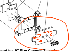
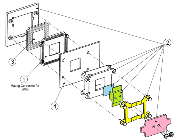
The package I have right now for my DMD is the one shown in the following picture
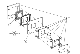
I want to address a couple of questions I have about it:
1. Are there guidelines or designs for how to add passive or active cooling units to this package? I have been looking around without no success but I always see posts talking about the "Design Search Tool" or the "Discovery Extranet" which I couldn't find.
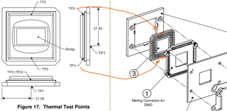
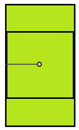
2. Are there any recommendations on how to put the sensors at the temperature test points? Which sensors should I use?
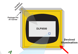
3. And my last question is about the incident light. Is there any issue I should be worried about if I illuminate the DMD from the opposite side? I would suppose the only change is that the On and Off states are swapped. See the next picture for an illustration.
Thanks in advance for your consideration.