This thread has been locked.

If you have a related question, please click the "Ask a related question" button in the top right corner. The newly created question will be automatically linked to this question.

DLP5530PGUQ1EVM: HDMI interface

Part Number: DLP5530PGUQ1EVM

Hello-

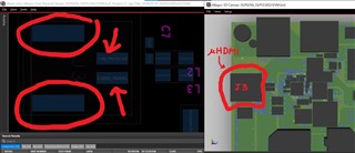
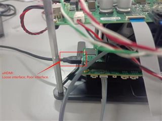
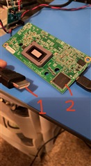
The micro HDMI interface has poor contact. How can I solve it?

It should be noted that there is no man-made damage to the micro HDMI interface. And I only have HDMI cable. I also tried to change a new cable but it still didn't work.

Hope to get a detailed solution as soon as possible!

Thanks,

yang

  • Hello Yang -

    What is meant by poor contact? Where is the poor contact - within the HDMI connector, or between the HDMI connector and the PCB? 

    Regards,

    Ross

  • It is between  the HDMI and the controller PCB of EVM.

  • Hello Yang - 

    Unfortunately there is not a quick solution for this issue. It seems like there is a poor mechanical / electrical contact between the HDMI connector and the PCB. Does your company have the ability to fix a PCB assembly issue - perhaps with a soldering job?

    If not, then the best solution that TI can offer is to issue a return for this part. Would you like for TI to help with the return process?

    Regards,

    Ross

  • Hello Ross-

    We can't accept the return plan. What should I pay attention to about the soldering job?

    Or can you give me a detailed introduction to OpenLDI (Flex connector)?

  • Hi Xia,

    OpenLDI may be difficult to use because it typically requires a custom board.

    If you have not yet soldered the uHDMI port, you may reflow/solder these pads on the board if it is just the HDMI to PCB connection. Below are three images to help locate the four solder pads, circled in red and pointed to by the arrows.

    Regards,
    Michael Ly

  • Hello Michael-

    Not this interface. The interface with problems is shown in the figure below:

  • Hi Xia,

    I'm sorry, I have shown controller power above! Here is what I should have shown:

    The HDMI header is J3, with its pins shown above.

    The images are from the zipped design files on the following TI product page if you would like to explore it more.

    If the HDMI connector is only loose on the outer four GND pins, I would first resolder those and test if the connector works. I would then move onto the other exposed pins and test once again. That way, you will not have to remove the entire HDMI connector and resolder everything. The last resort should be the pins closest J3 text in the picture above.

    I'm very sorry that the connector has poor contact, though, and I hope that you're able to get it up and working soon!

    Regards,
    Michael Ly

  • Hi Xia,

    Have you been able to solder the HDMI connector as intended?

    Regards,
    Michael Ly

  • Hi-

    Because sometimes when I try to firmly insert the HDMI interface with my hands, it has a small probability that it will work properly. Therefore, I think it is not the solder joint problem that causes poor HDMI contact. It may be the quality of the microHDMI socket. What's your opinion?

    To test my idea, can you tell me its model parameters? 

    What other suggestions or ideas do you have?

    Hope to solve the problem of poor contact as soon as possible! Please hurry up!

    Thanks,

    yang

  • Hi Yang,

    I talked with my team today, and I was told that you could possibly check the DVI receiver to check if your HDMI connector is working. Though it may be difficult since the uHDMI connector is so small, you could connect the HDMI cable and probe the opposite end of the connector (that would have gone to your host or computer) while simultaneously probing the signals coming from the DVI connector that receives the HDMI signals from the board.

    You can see that the micro HDMI blocks are on the left, and the signals are taken through the DVI receiver, which then outputs the RGB, sync, clock, and DEn signals.

    In the layout above, you can see the uHDMI and relevant nets for the schematic.

    Additional layout pictures can also be found below:

    If this does not work, an external PCB manufacturer that specializes in assembly/soldering may be able to solder a new micro HDMI connector or solder your existing board.

    TI could possibly lend you a spare board that you will eventually return as well.

    Yet another option is to order a replacement if we fail to figure out what is causing the HDMI to not work as intended.

    If you decide to take measurements, may you please save those scope shots for TI to view? We would also like to see a picture of your micro HDMI connection on both top and bottom of the board, too, if possible.

    Best regards,
    Michael Ly

  • (1)Sorry, I didn't understand how to probe the signals coming from the DVI connector that receives the HDMI signals from the board. Could you explain it in more detail? (We didn't do this test. The following is only for wiring :)

    (2)Does the spare board refer to the controller PCB that can work normally? It would be great if you could send us a spare board and finally work normally. Because we have purchased three sets of EVM at TI, but unfortunately they have the same problem. We are deeply troubled by this! 

    Could you please arrange the delivery of spare boards as soon as possible? 

    Please let me know the detailed arrangement and I will try my best to cooperate with you. To realize the normal operation of EVM.

    Thanks!

    (3)In addition, can you tell us the model of the UHDMI socket at the position shown in the figure below?

    Thanks again!

  • Hi Yang,

    I'm sorry for the delay.

    1. Sorry, I didn't understand how to probe the signals coming from the DVI connector that receives the HDMI signals from the board. Could you explain it in more detail? (We didn't do this test. The following is only for wiring :)

    |
    I apologize for not being clear enough. What I had meant was that the third picture in my previous reply had outputs of the DVI receiver labeled. If you were to probe those lines and then also have a micro HDMI cable attached, you should ideally see a similar signal coming out of the receiver as you would the end of the HDMI cable that should be plugged into your computer. This test could rule out whether or not there is an HDMI signal even coming out of the receiver and if the HDMI cable is receiving the signals if a signal is present.


    • Does the spare board refer to the controller PCB that can work normally? It would be great if you could send us a spare board and finally work normally. Because we have purchased three sets of EVM at TI, but unfortunately they have the same problem. We are deeply troubled by this! 

      Could you please arrange the delivery of spare boards as soon as possible? 

      Please let me know the detailed arrangement and I will try my best to cooperate with you. To realize the normal operation of EVM.

      Thanks!


    |
    I have also talked with my manager to check if TI can send a spare. This is not possible, but TI may swap a board with you if you wish to return yours for a new one. I will send you a connection request if you wish to do so.


    • In addition, can you tell us the model of the UHDMI socket at the position shown in the figure below?
    |
    Here is a digikey link to the micro HDMI connector that we have used in our BOM for the DLP553x controllers. This should give you the parameters you need as well as pin outs if you are able to probe them.

    The two/three quickest options would likely be to order the part and try to solder the new HDMI yourself again, have an external party solder it, or to have TI replace it.

    Please let me know where you would like to go. I am sending you a connection request right now to speed things along if you wish to get a replacement.

    Regards,
    Michael Ly

  • Hi again Yang,

    Have you been able to accept my E2E friend request?

    I would also like to use this time to clarify that if you do wish to get a replacement, you will need to return the EVM and go through the return process. We can talk about the details privately.

    Regards,
    Michael Ly

  • Hello -

    Sorry for the late reply! I don't know why I can't go to the corresponding interface by pressing Reply.

    Due to the COVID-19 epidemic, we are about to enter the "holiday state", the return program may not be arranged temporarily. The return arrangement can only be postponed.

    I will try Scheme 1 and Scheme 3 first. However, I may not be very clear about the specific implementation details of the signal test in Scheme 1, and there may be limitations to existing conditions. May be difficult to carry out. 

  • Hi Yang,

    This is a strange occurrence. I am not able to reply to the last few posts on this thread. The 'reply' button does not seem to function as intended, and my screen looks just like yours. Thank you for update on holiday as well. I will be on holiday on December 26th and January 2nd.

    As for checking the connection, I was told today that it would be better to just perform a continuity test. Here is an example of where you may be able to probe. Please make sure you probe both sides when doing the continuity test.

    Using a multimeter, you can perform a continuity test to see if the pins are indeed connected. There may be some EMI filtering / ESD protection chips that interrupt the continuity, however, as seen in the picture below. I will see if I can find these on the physical board when I am back in the lab tomorrow. Here is an image to help explain:

    I would check the area in red first to be safe.

    I hope this is what you were asking about. Otherwise, may I take a step back and ask what you are not clear about? I apologize if I have misunderstood.

    Regards,
    Michael Ly

  • Hi again Yang,

    I found the HDMI EMI filtering and ESD protection chips below:

    I will be closing this thread for now since I think I have provided you with enough options to get the board fixed:

    1. Soldering a new micro HDMI back on or soldering the current one you have again with the micro HDMI link here
    2. Having an external party that specializes in soldering solder for you
    3. Testing continuity of signals
    4. Issue a return to TI to allow us to send you a new board

    If you have a new question regarding these, please feel free to open up a new thread, and we will be happy to help. If you'd like to continue, we may take this offline, and I have sent you a request to connect.

    Best regards,
    Michael Ly