Part Number: DLP3030-Q1
The PGU red light has obvious jitter under low brightness setting. What might be the cause?
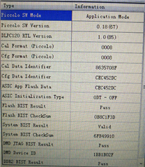
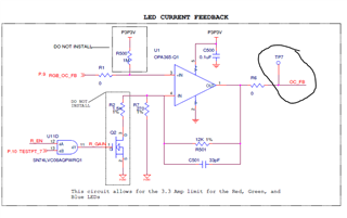
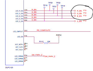
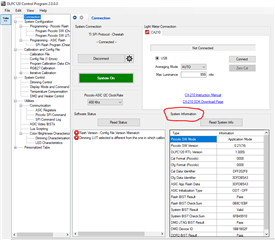
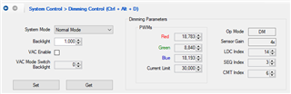
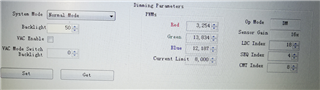
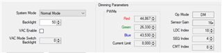
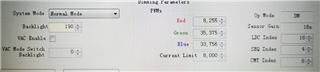
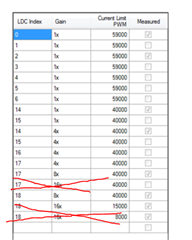
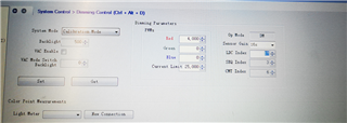
The setting is:
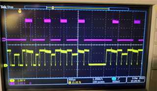
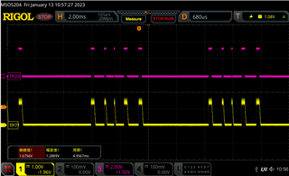
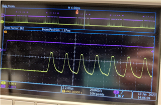
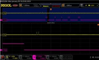
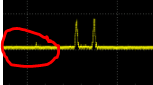
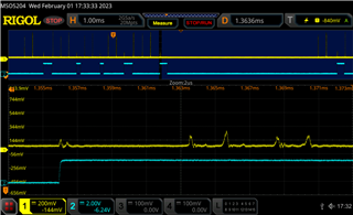
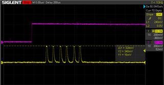
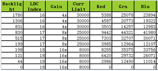
The phenomenon is:
Looking forward to your reply.
Part Number: DLP3030-Q1
The PGU red light has obvious jitter under low brightness setting. What might be the cause?
The setting is:
The phenomenon is:
Looking forward to your reply.