This thread has been locked.

If you have a related question, please click the "Ask a related question" button in the top right corner. The newly created question will be automatically linked to this question.

DLP7000: The time sequence of 8 bit grayscale frame

Part Number: DLP7000

Hello,

       As you mentioned in the thread “e2e.ti.com/.../dlp7000-how-to-achieve-maxim-pattern-rate-for-dlp7000-8bit-greyscale”, the one of the illumination modulation is as follow:

  • MSB -- on for 8 * 43 µs
  • MSB - 1 -- on for 4 * 43 µs
  • MSB - 2 -- on for 2 * 43 µs
  • MSB - 3 -- on for 43 µs
  • LSB + 3 -- on for 1/2 of 43 µs
  • LSB + 2 -- on for 1/4 of 43 µs
  • LSB + 1 -- on for 1/8 of 43 µs
  • LSB -- on for 1/16 of 43 µs

     There are some questions about  how to realize this modulation on the dlp7000.

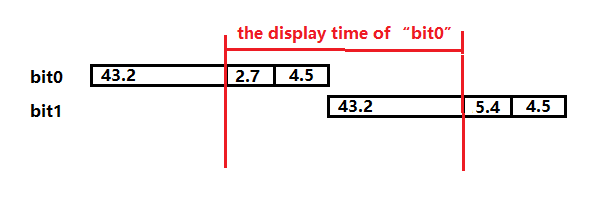
  • First, the illumination of "bit0" is 1/16*43=2.7us,the display time of "bit0" is 2.7+4.5+43.2=50.4us,so it is not equal with 43.2us.so the total time of one frame is longer than 817us.is that correct?If not,could you give me some details of  the correct sequence. If it is correct,how to do the second modulation.(LSB-- on for 1/32 of 43us). 43*(1/32)= 1.35us.
  • Second,I only found one way to make DMD from "1" to "0",that is "clear block" command.And anything else? If use this command,"mcp(reset)" has to be used,so the length of the display time is more than 43.2us.So that the rate should not equal with 817us. 

  • Hey Jack,

    Thank you for the link to the thread and subsequent questions.

    For clarification, could you define your meaning of 'making the DMD from "1" to "0"?

    Best,

    Aaron

  • Hello Aaron,

          I am sorry for my best English.”1“ means the value of the DMD SRAM is "1",and represents the DMD state is on. 

          Actually,I want to get  a complete sequence  of  8bit grayscale on DMD ,and then i can control every signal which is connecting with FPGA.

  • Oh,I means my bad English.Innocent

  • Jack,

    We are discussing this internally and will get back with you next week.  Monday is a holiday for us.

    Fizix

  • Hello again Jack,

    Thank you for your patience as we discussed this.  After discussing, please note that the information in that post was oversimplified for the purpose showing that if you have a source that can be modulated very fast it is possible to run at the load and reset time for each bit.  It does not account for the rise and fall time of a modulated source, nor does it account for the switching time of the DMD.

    If you have a source that can be modulated you do NOT want to use block clear, as that will only add time to your frame/sequence.  The purpose of the block clear is primarily for use with a continuous illumination source such as a lamp.

    The basic sequence is this for an 8-bit grayscale, but is easily extended or shortened for more bits or less bits.

    You want to make sure that the time that each bit is exposed to light goes as follows (we will track from the least significant bit (LSB):

    • LSB - This will be the shortest amount of light time that your illumination source can be modulated to.
    • LSB + 1 will be twice as long
    • LSB + 2 will be four times as long

    |

    • LSB + n will be 2^2 times as long where for 8-bit this will be 2^7 = 128

    For each bit you will at minimum need to turn off the illumination if the exposure time is less than the load and reset time of the next bit.  More complex sequences can be made depending on what your requirements are.  There is a whole science around building sequences.

    The things that you will need to characterize are the rise and fall times of your illumination source. and the DMD switching speed from on to off and from off to on.  These vary by DMD and are also very dependent on your optical system parameters, such as F#, telecentric vs non-telecentric optics.

    Please send me a friend request if you would like to discuss this more offline.

    Fizix