This thread has been locked.

If you have a related question, please click the "Ask a related question" button in the top right corner. The newly created question will be automatically linked to this question.

DLPNIRNANOEVM: Not able to reroute the scan button to the expansion connector

Part Number: DLPNIRNANOEVM
Other Parts Discussed in Thread: DLPC150

Hi Experts,

I'm trying to reroute the scan button (PQ3) to expansion connector (pin 8, PK3), following the instruction of the related thread (provided by Pedro Gelabert). However it isn't work, here is the detail:

1. It is successful to reroute the green LED, by changing if 1 ---> if 0 in common.h, line 203. Everything works fine, the outside LED blinks, scan process works fine by PC GUI:

/**
* Compiler switch to remap GREEN LED
*
* 0 = Green LED output to Expansion Connector J3 pin 6
* 1 = Green LED on Tiva Board
*/
#if 1
#define GREEN_LED_TIVA_BOARD // PF5
#undef GREEN_LED_EXP_CONN
#else
#undef GREEN_LED_TIVA_BOARD // PA5
#define GREEN_LED_EXP_CONN
#endif

2. However, when do the samething for the scan button and burn the firmware to NANO, it doesn't work. The NANO is even not able to connected to PC GUI, not to mention that no response to the external button which connected to PK3.

Because the problem is NANO is disconnected, and on another hand, the reroute for green LED works fine, I guess the problem might be in the code level. However I can't work out what is the problem by myself, could you kindly help?

I only changed the line 195 from if 1 to if 0, following the instruction in FAQ. But the NANO is disconnected, with this only one change:

      • Example to remap the scan button to Expansion Connector J3 pin 8, change line 195 from
/**
 * Compiler switch to remap Scan button 
 *
 * 0 = Scan button input from Expansion Connector J3 pin 8
 * 1 = Scan button input from Scan button on Tiva Board
 */
#if 1
#define SCAN_BUTTON_TIVA_BOARD     // PQ3
#undef SCAN_BUTTON_EXP_CONN
#else
#undef SCAN_BUTTON_TIVA_BOARD     // PK3
#define SCAN_BUTTON_EXP_CONN
#endif

to:

#if 0
#define SCAN_BUTTON_TIVA_BOARD     // PQ3
#undef SCAN_BUTTON_EXP_CONN
#else
#undef SCAN_BUTTON_TIVA_BOARD     // PK3
#define SCAN_BUTTON_EXP_CONN
#endif
  • Dear All,

    And I'm confident on the ccs version and firmware version, because I've tried some other modifications like turn on the bluetooth on startup, reroute the green LED and they all works fine, so I think it is not ccs or firmware version problem. I'm using ccs 12.2.0 and the offical firmware DLPNIRscanNanoSoftware_2.1.0. But like mentioned above, only change the line 195 in common.h and keep all other codes the same, will cause disconnection between NANO and PC GUI.

    Much appreciated for your kindly help,

    Sichen Bian

  • Hello Sichen,

    Welcome to DLP forum and thank you for your interest in DLP technology.

    Our team will look into this and get to you by middle of next week.

    regards,

    Vivek

  • Hello Sichen,

    PK3 is already being used by UART4 as CTS pin as part of its initialization. This could lead to boar init errors.

    Please comment out the UART initialization to avoid initialization errors.

    Regards,

    Akhil

  • Hi Akhil,

    Thanks for your help, however after I tried to comment out some line related to UART init and uploaded it to the EVM, the EVM turns to disconnected/no response for USB cable. Maybe I made some mistake. Could you help this disconnected issue,too?

    I tried "press and hold" the scan button but there's no response. Here's what I've done, I press and hold the scan button before powering up, then I inserted the USB cable, then I keep the holding for another 5 secs or so, then I release the scan button. However, the uploaded of firmware is still stuck at 10%. I tried to use JTAG connector with ccs, and in CCS it will show can't connect to the target. Do you know why this procedure failed? Is it because I don't have a 2.1.0 firmware in EVM, or something I made mistake by the pressing button? Is there any indication when the EVM is in bootloader mode?

    I Also found this thread https://e2e.ti.com/support/dlp-products-group/dlp/f/dlp-products-forum/811905/dlpnirnanoevm-device-not-recognized/3009995#3009995, and will try it after I receive the SD card. Will this work? And is there any other way to save the EVM?

    Above, thanks!

    Sichen

  • And I read this thread, too:https://e2e.ti.com/support/dlp-products-group/dlp/f/dlp-products-forum/845204/dlpnirnanoevm-worng-firmware-nirscan-nano-dead-forerever, it seems using JTAG debug probe can solve this. I have a j-link emulator, and it works while uploading .out file to EVM, so the hardware should be no problem. But after the EVM have a bad firmware, I can't connect the EVM through EVM, too. Do you know how does the above thread solve the problem?

    Thanks again!

  • Sorry, there's a type: I can't connect the EVM through EVM, too. ---- I can't connect the EVM through JTAG&CCS.

  • Hello Sichen,

    Please allow the team until next week to form a response. 

    In the meantime, you may want to consider attempting to re-flash your EVM with the SOIC clip as described on this FAQ post.
    Regards,

    Austin

  • Hi Austin,

    Many thanks and waiting for your update. Currently I don't have such device to do it, if there's easier way to recover it, it's best.

    Thanks,

    Sichen Bian

  • Hello Sichen,

    We do not have an update currently. Thank you for your patience.

    Regards,

    John

  • Hi John,

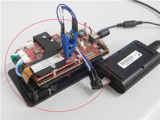
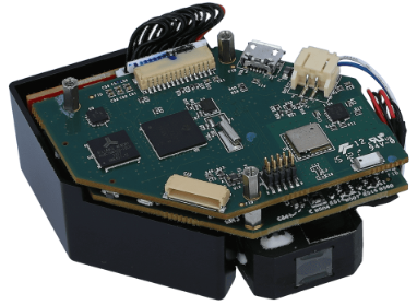
    Thanks, so the only choice is to use SOIC clip, I read the instruction, and have one more question, in the picture, it seems the device is not DLPNIRNANOEVM. Do you have a picture of hardware connection for DLPNIRNANOEVM?:

    DLPNIRNANOEVM is like this pic:

    Sichen Bian

  • Hello Sichen,

    For programming DLPNIRNANOEVM with the SOIC clip, please refer to the EVM reference design TIDA-00554 and follow the instructions mentioned in the SPI Device Flash Via SOIC Clip Guide

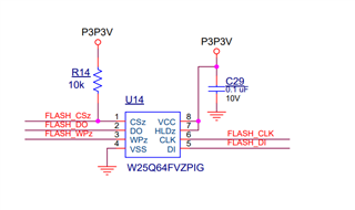
    The SPI flash device used on the DLPNIRNANOEVM (refer to below picture) is similar to the one shown in the user guide above. 

    I hope this helps.

    Regards,

    Lori 

  • Dear Lori,

    Thanks for your explaination, and I do found the W25Q64FVZPIG in the BOM of DLPC150, which is DLP controller board for DLPNIRNANOEVM.

    However, I'm confused why it will be useful, because I think for my machine, the problem is on the Microcontroller board instead of DLP controller board.

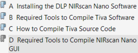
    The root cause is, I modifed the UART initialization code in this link:www.ti.com/.../tidcc48. I followed Appendix A-D in DLPNIRNANOEVM user guide. So I'm confuesd, it seems not relevant to flash the firmware for DLP controller board, what I need to do is to flash the firmware for Microcontroller board. 

    Thanks in advance again!

    Sichen Bian

  • Hi All Experts,

    Sincerely thank you all for helping my issue, I just happen to fix it. I changed the power supply from USB connection to the external battery power connector(J6), then JTAG can recognize the device. I guess maybe the wrong code has an influence on the USB connection.

    Because my device has restore to normal, could you provide a guidence/code example about how to reroute the scan button? Akhil mentioned that:

    PK3 is already being used by UART4 as CTS pin as part of its initialization. This could lead to boar init errors.

    Please comment out the UART initialization to avoid initialization errors.

    But I don't now which line should I comment out. A code example will be very helpful;

    Above, thanks!

    Sichen Bian