This thread has been locked.

If you have a related question, please click the "Ask a related question" button in the top right corner. The newly created question will be automatically linked to this question.

DLP3010EVM-LC: DLP3010EVM-LC

Part Number: DLP3010EVM-LC
Other Parts Discussed in Thread: DLPA2005, DLPC3478, , DLPDLC-GUI, DLPC-API

Application: Customize the display board and main board PCB into a single PCB within certain dimensions (user requirement), to produce an array of 1D patterns at a fixed rate and also trigger cameras.

EVM: DLP3010EVMLC

Major components required on the customised PCB would be Cypress USB to serial converter, MSP430, DLPC3478, DLPA2005 and Flash Memory. (Kindly correct if otherwise)

The following queries are considering that since we are making a customised PCB, a need to establish a connection with the same will be present and individual ICs/microcontroller will need programming.

Query No.

Query

Source

1.

What driver will be needed to establish a communication with the customised system?

DLPU074A – Section 3

2.

a.         Is the dlpc347x Visual Studio project file to be burned on the 32Mb flash memory (W25Q32JVSSIQ) present on the display board.


b.        ‘TI provides software as a firmware image. The customer is required to flash this firmware image onto the SPI flash memory’. By what name is this image available? How to incorporate this file in the customised PCB?


c.         ‘A flash component is required to store patterns, the software, and the firmware in order to control the DLPC3478 controller’. What is the significance of this software and by what name is it available? How to incorporate this file in the customised PCB?


a. DLP-PICO-DLPC34XX-API — DLP® PicoTm API for the DLPC34XX controllers >> Order and Start Development


b. DLPS111C – Section 7.5 Programming


c. DLPS111C – Section 8.2.1.1 Design Requirements


3.

What is the significance of ‘DLP3010EVM-LC_Firmware_v8.0.0_Installer’?


Is it necessary step for the customised PCB?

DLP3010EVM-LC-FW — DLP 3010 Light Control Firmware >> Order and Start Development


4.

What is the significance of ‘DLPx010EVM-LC MSP430 Software Setup’ file?

DLPX010EVM-LC-MSP430-SW — DLPx010EVM-LC MSP430 HDMI Sample Code >> Order and Start Development


5.

Will the Cypress IC, MSP430, DLPC3478 and DLPA2005 also need to be programmed.


6.

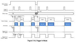
a.       Are the TRIG_OUT_1 and TRIG_OUT_2 used to control synchronization with 2 cameras respectively.

b.       What is the significance of these signals in Internal Pattern streaming mode? What is frame trigger and pattern trigger?


7.

In order to generate a particular pattern, is it okay if we make use of DLPDLC GUI’s internal pattern mode and download the firmware which can later be burned on the respective IC?


Requesting you to let me know if I missed any critical element necessary for the customised PCB development.

  • Hello User,

    Please allow the team some time to go through these questions and get back to you.

    Regards,

    John

  • Hello User,

    We appreciate your understanding. Please wait for a reply to this page.

    Kind regards,

    Austin

  • Hello User,

    These questions depend on how you want to design your custom board. TI provides the reference design (TIDA-080003) for DLP3010EVM-LC . Please see the answers below for reference:

    1. DLPU074A – section 3: For DLP3010EVM-LC, you need to download DLPDLC-GUI tool to communicate with either EVM or custom board through I2C commands. Please follow the instructions for software installation. The needed driver should include in the installation. 

    2. a) The DLPC-API is an alternative method to control the DLPC34xx chipset. It is a C-language routines to use in a DLP system. However, you have the option to use DLPDLC-GUI tool to control the EVM/custom board through SPI and I2C commands. It depends on the communication interface you design. Ultimately, the DLPC-API uses the same I2C to communicate with the EVM/custom board as the GUI does.

        b) Please find the available firmware images on TI DLP Pico Firmware Selector page. Different firmware is required for different chipset combinations (such as different PMIC device, different DMD pin mapping). You are able to use DLPDLC-GUI to program the firmware image onto the board. Or you have option to use SOIC clip to flash the firmware image onto the SPI flash device. Please refer to the E2E [FAQ] SPI Flash Device with SOIC Clip Guide.

        c) Please refer to above answer for part b). The firmware and controller software programmer’s guide are available on DLPC3478 Product page.

    3. Please refer to question 2. TI provides software as a firmware image. The controller and its accompanying DLP chipset require this proprietary software to operate. However, the user has some level of ability to change the firmware settings.

    4. Please refer to  [FAQ] Pico MSP430-MCU Flash Quick Guide. The document shows the guidelines for programming the MSP430.

    5. You don’t need to program DLPC3478 and DLPA2005 separately. The firmware image provided on question 2 b) include the proprietary software to operate.

    If you need to program Cypress IC, please find information on Cypress website. We do not have specific support for programming Cypress

    If you need to program MSP430, please refer to question 4.

    6. a) Yes, you can understand like that. 

       b) You have option to enable or disable the Trigger out signals. Please refer to DLPC3478 datasheet section 7.3.2.2 to better understand the trigger signals. 


     7.  Yes, in internal pattern mode, the patterns can be pre-loaded in flash memory and a host command is sent to DLPC3478 controller to display the patterns. Please note the internal pattern mode only supports 1D patterns. 

    I hope this helps. 

    Regards,

    Lori