


Hi,
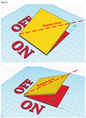
I draw a graphical representation (see Figure1) to illustrate the tilt orientation between the micro-mirror and the DLP4710LC backplane after referring to the datasheet of DLP4710LC. It illustrates that the tilted axis is NOT coplanar with the DLP4710LC backplane. Is this correct?
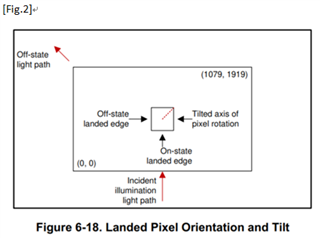
If figure1 is correct, then what’s the logic behind illustrating the tilted axis with red dashed line that does not connect a vertex to another vertex? (Fig.2)
Thank You!