This thread has been locked.

If you have a related question, please click the "Ask a related question" button in the top right corner. The newly created question will be automatically linked to this question.

DLPLCR4500EVM: Operating Lightcrafter without RGB LED Light Engine

Part Number: DLPLCR4500EVM
Other Parts Discussed in Thread: DLPC350, , DLP4500

Greetings everyone,


I have refer to the video below (Youtube Video) when working with Lightcrafter.

Link: https://youtu.be/RxgmGkNsqvk


I need to check with you is there any special settings or configuration in hardware/software if the Lightcrafter does not operate with RGB LED Light Engine? I have tried using configuration same with end-user. We straight shoot the green laser to the DMD Display and put on the paper to display reflected light. I have attached the video for you to verify is the setup and expected pattern should be like that? Also, it will be great if you can show what pattern should appear. Does it same as in the video?

Video Link: https://drive.google.com/drive/folders/1JVyNqUth4s38xCvAKGoh843VhLpCpupx?usp=drive_link

Kindly assist me on this.

Thank you

  • Hi Azri,

    Welcome to the E2E forums and we hope to assist you with your questions. 

    So did you have a DLPLCR4500EVM and then removed the optical engine and trying to replace the light source with lasers? Do you have an optical engine built around lasers or are you just trying to test with a laser standalone? Is the laser manually controlled or is it connected or wired to drivers connected to the DLPC350.

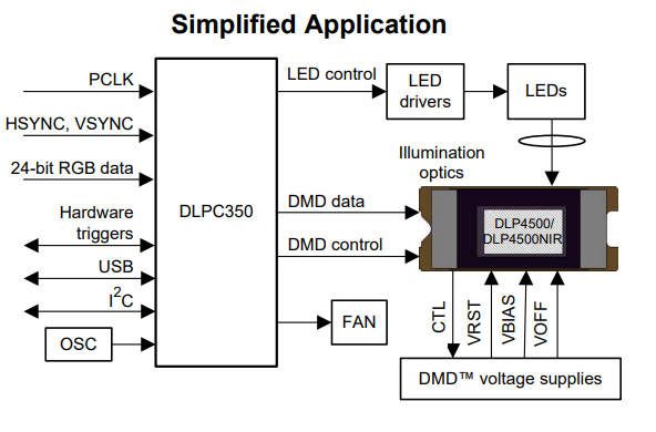
    Are you using the lightcrafter 4500 gui? The gui is meant to communicate with the EVM by sending commands to the DLPC350 to perform actions to the DMD or LED driver to control the LEDs. What image or display are you sending to the DMD that may determine what pattern you will expect to see once the laser is applied. 

    Please also see this other E2E posts for more information that may be helpful.

    https://e2e.ti.com/support/dlp-products-group/dlp/f/dlp-products-forum/848860/dlp4500-how-to-synchronize-the-pulsed-laser-and-the-dlp-4500?tisearch=e2e-sitesearch&keymatch=4500%2520laser#

    Thanks,

    Alex Chan

  • Greetings Alexander,

    Yes I have DLPLCR4500EVM and removed the LED light engine and replace the light source with laser (green colored). I also just test with a laser standalone. The laser manually controlled which can be turn on and off, and the laser have no options to varies output power, it is fixed.

    Yes, I am using the Lightcrafter GUI (latest version installed). I am currently test the Lightcrafter using "Pattern Sequence" mode. I follow step by step as in the Youtube video (attached in the link previously). It seems like the GUI can communicate with the hardware and LED blinking indicates the PCB is in good condition. The DMD display is connected to the Lightcrafter's PCB/Microcontroller using flex cable given by Texas Instruments itself. 

    Basically, the configuration is to shoot the green colored laser to the DMD display and project the reflected light to the plain paper and observed the changes or the results of the pattern that has been program by Lightcrafter GUI. 

    Result on DMD display: There are several patterns appeared on the DMD display (black colored line) but at some time, the pattern is gone by itself and it is not moving.

    Result on plain paper that display reflected light: The pattern can be seen change from one pattern to other pattern (video uploaded to Google Drive link as in previous conversation). Need to verify this results is okay or not as there are no reference on the actual pattern looks like.

    Kindly assist me. Thank you.

  • Hi Azri,

    Thanks for the background information. I will look into this issue more with the team. Thanks for your patience.

    Thanks,

    Alex Chan

  • Hello Azri,

    Thank you for your patience. The DLP4500 DMD is side illuminated and mirror tilts by 12 degrees. Please refer to the page 23 of DMD datasheet for details.

    DLP4500 .45 WXGA DMD datasheet (Rev. B) (ti.com)

    The laser needs to illuminate the DMD at 24 degrees along small edge of DMD as shown in datasheet, The ON state (projected patterns) will at zero degree.

    From the video , I can not verify if above conditions are met ie Laser is at 24 degrees along short edge and paper is parallel to DMD surface.

    Another issue with collimated laser - a collimated laser will show multiple diffraction order images on the screen.  In order to avoid that you need to use optics to expand the laser beam and image it on DMD. Your best bet may be to use the existing optical engine along with optics. i.e just replace green LED with laser and not drive other two LEDs.

    regards,

    Vivek