This thread has been locked.

If you have a related question, please click the "Ask a related question" button in the top right corner. The newly created question will be automatically linked to this question.

Display mode not coming up - DLP5531

Other Parts Discussed in Thread: DLPC230-Q1, TMP411

Hi Ross,

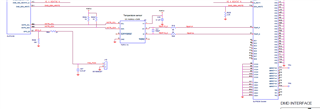
After careful review of the circuit diagram, I found that the ALT-MADR-SEL input should be low, but we set it to high. Thank you very much for helping us solve this problem. But there seems to be a new problem. Our board is now in STANDBY mode and cannot enter DISPLAY mode. I want to set it to DISPLAY mode, but it tells me it needs to RESET. And I can't seem to reset it.


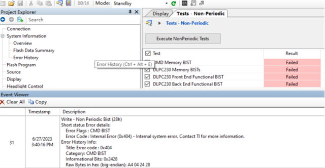
I tried to make it do Non-Periodic Test, but it failed all the time.


 I hope you can continue to help me solve new problems. I really appreciate it.

Thanks,

Cherry

  • Hi Cherry -

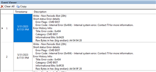
    As soon as you notice that it enters STANDBY mode, please read the Error History information and share this information:

    This will often tell us the root cause of the error. 

    One additional thing we can try is to disable the Non Periodic BISTs in the Composer project, and see if this is able to successful transition to DISPLAY mode.

    Regards,

    Ross

  • Hi Ross,

    I disabled the Non Periodic BISTs in the Composer project and rewrote flash in the CONTROL PROGRAM. But it didn't work. The error is as follows:


    When I want to manually set it to go into DISPLAY mode. It will report the following error:

    Regards,

    Cherry

  • Hi Ross,

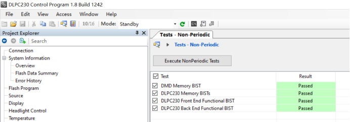
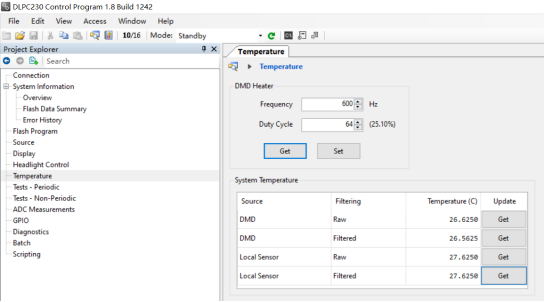
    After I set the TI board to STANDBY mode, the Non Periodic BISTs test passed. The system temperature can also be obtained.


    Our board has removed the circuit of the DMD HEATER. And then we don't get the temperature of the system. Will this part affect the reset?


    Regards,

    Cherry

  • Hi Cherry, Ross is out for the next couple of days returning on Monday.  I think we need his help to answer this next question.  However, the non-periodic BIST only operates in Standby mode.

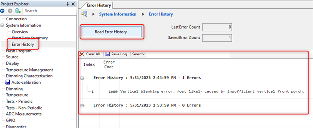
    The reason that the device is going into standby mode is due to "incorrect vertical blanking".  Do you have a valid input video source?  If not , then the DLPC230 automatically switches to standby mode.  The timing of the video input must match input timing as shown in the DLPC230 datasheet section 6.   Please check this point and let us know your results.

    Thanks,
    Jason

  • Hi Jason ,

    I didn't ask the board to pick up the video source because I thought it would automatically go into DISPLAY mode and display my startup image after I downloaded FLASH. I think its video configuration interface is already configured in the FLASH file. Or do I need to reconfigure the video interface myself, and if so, where should I go?

    Thanks,
    Cherry

  • Cherry,

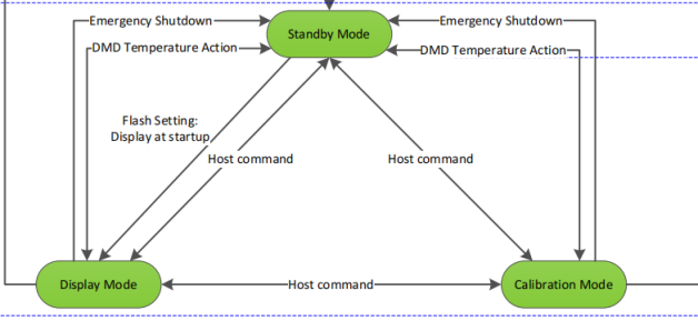
    The DLPC230-Q1 has many diagnostic features to ensure that the system is operating safely.  Thus, if the input video is not "valid",  then it will automatically switch to standby mode.  However, it will not automatically switch back to display mode until it is commanded to do so.  Thus, once the system is power on and the video is valid and present, then you can switch to display mode.

    Please see the user's guide section 4.1 to explain how to use it in more detail.  https://www.ti.com/lit/ug/dlpu041f/dlpu041f.pdf

    Thanks,

    Jason

  • Hi Cherry -

    Looking at your messages, it seems the main error code you are receiving is the TPS99000 Interface BIST. (There is discussion above about the vertical blanking, but actually that message comes from the screenshot example that I sent from my system. )

    Typically this TPS99000 Interface BIST only occurs for HUD Composer projects. And since you are working with a DLP5531 which is a Headlight (i.e. not HUD) project, this is puzzling. Can you please share the .xproj Composer project that you are using?

    Thanks,

    Ross

  • Dear Ross,
    I have only used DLP control program and DLP composer. The FLASH file I import in DLP control program is the FlashImage_p55_1152_VSP_HL.bin file. The file I opened in DLP composer is the 2021-02-05_Release_1.5.0.0.xproj file. I can use TI's EVM after importing these files.I can't seem to upload the engineering files, but the engineering files are also shared with me by TI.
    Thanks,
    Cherry

  • HI Jason,

    After looking at the file you mentioned, I found that there may be several reasons for staying in STANDBY mode:

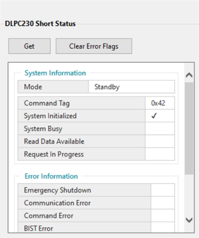
    In the upper computer, I used DLP230 to read the short state and found that the system did not enter the emergency shutdown. I can't get it into DISPLAY with instructions. I directly put the bin file into FLASH, Flash Setting should be fine. As for the DMD temperature operation, I don't know if the DMD heater I removed will have any effect.

    There is a paragraph in the documentation that describes standby mode, I wonder if non-periodic BISTs fail and I can't get in the DISPLAY? How can I solve this problem?

    Thanks,

    Cherry 

  • Hi Cherry,

    The DMD Heater is not required, but the DMD temperature sensor (TMP411) is required.  Did you connect this circuit?  Can you read the DMD temperature?

    Thanks,

    Jaosn

  • Hi Jaosn,

    This is the DMD temperature sensor (TMP411) on our board. I have connected this circuit and it seems to be no different from TI's.

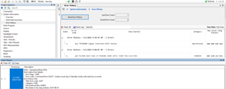
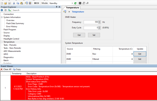
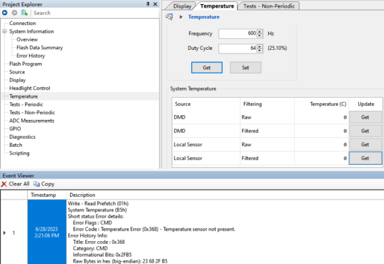
    I can read the Temperature frequency and duty cycle, but I cannot read the system temperature. The error is as follows:

    Thanks,

     Cherry

  • Hi Cherry,  OK thanks for the update.  The fact that the DLPC230 cannot detect the temperature sensor is one reason that the system will stay in standby mode.  There are different options for the TMP411 device there is actually TMP411A, TMP411B, TMP411C.  However, only the TMP411A will work with the DLPC230 as the IIC address is different.  Please check that the TMP411A is truly installed on your PCB and not Version B or C.

    Thanks,

    Jason

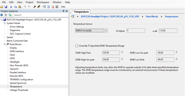
  • Hi Cherry - 

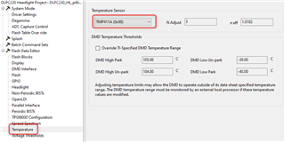
    Please also confirm that you have the proper TMP411 configuration in the Composer project:

    Regards,

    Ross

  • Hi Rose,

    Here is my TMP411 configuration in the Composer project, which seems to be the same as yours.

    Regards,

     Cherry

  • Hi Jaosn,

    The temperature sensor model we used is TMP411ADGKR, and I see that TI uses TMP411AQDGKRQ1, which is different from ours. Is it because of this that the sensor cannot be used?

    Thanks,

     Cherry

  • Hi Cherry,

    I looked through the datasheet and register maps and both parts seem similar.  With that said, we have only tested the TMP411A-Q1 device in our system.  The error code is x368 - temperature sensor not present.  This means that the DLPC230 cannot get any response from the TMP411 device.  Is the DMD connected properly to the signal TEMP1P and TEMP1N?  Are you able to try the TMP411A-Q1 device in your system (swap from the TI EVM)?  

    This error is very specific and it is related to the TMP411 device, so it must be a problem with this device - either the connection of the device, the version of the device, or connection to the DMD.  Please check these points as a next step.

    Thanks,

    Jason

  • Hi Jason,

    My dlp230 failed to communicate with TMP411A. After being powered on, MSTR_SCL and MSTR_SDA do not generate any signal after being pulled high. My bin file configuration was the same as TI's, and there didn't seem to be much of a problem on the circuit. This is very confusing to me. I hope I can get your help.

    Regards,

    Cherry

  • Hi Cherry,

    The good news is that we have identified the problem more clearly.  There are two things the I can think of to try to check:

    1. Measure the pull-up resistors R90 and R91.  Are the values 1KOhm?  Are they installed properly?

    2. Are you able to swap out the part on your board to the PN TMP411AQDGKRQ1?  Even though the non-Q1 part should work, we have never tested it in our lab.  

    Hopefully, you can find the issue soon.

    Thanks,

    Jason

  • Hi Jason,

    I measured pull-up resistors R90 and R91. They have a value of 1KOhm and are installed correctly. Then I took the TMP411 off our board. The IIC lines that the DLP230 communicates with the TMP411 are connected to pull-up resistors. I would like to know if dlp230 will send a signal out through the IIC cable when it is powered on. My dlp230 software is configured fine, but the IIC line is not detecting any signal (including data and clock).

    Thanks,

    Cherry

  • Hi Cherry,

    The DLPC230 will initiate a read command, but the TMP411 has to be connected to send back and "acknowledge" command.  Otherwise, the DLPC230 will stop sending commands immediately and just report an error.

    Did you try to reconnect the TMP411AQDGKRQ1 onto your PCB?

    Thanks,

    Jason

  • Hi Jason,

    If the DLPC230 initiates the read command first, then I should be able to detect the waveform signal through the oscilloscope. However, after the power on, we can only detect the iic signal instant pull up, and do not see other waveforms. Since there is only one piece of TMP411AQDGKRQ1 on the TI board, we have not replaced it on our board for the time being.

    Thanks,

    Cherry

  • Hi Jason,

    Or is it because the previous step was not done correctly, resulting in the dlp230 program did not execute here, and did not detect the DLP230 read command signal?

    Thanks,

    Cherry

  • Hi Jason,

    We failed the non-Periodic test. Could dlp230 have failed to communicate with the temperature sensor as a result of its failure?

    Thanks,

    Cherry

  • Cherry,

    I am not sure exactly.  We have never run this test.  Yes, I would expect the periodic BIST to fail immediately when there is not any TMP411 installed.

    These parts are not expensive and readily available.  Can you just buy or request a few samples https://www.ti.com/product/TMP411-Q1/part-details/TMP411AQDGKRQ1?

    Seems like we are spending so much time on this topic and it be easier just to put the correct part onto the board.  We know that the correct part works.  Our recommendation is to use the TMP411AQDGKRQ1.  Please try this part. 

    Thanks,

    Jason

  • Hi Jason,
    I bought TMP411AQDGKRQ1 a week ago and used it. But it still doesn't seem to be communicating with the DLPC230. Just like the signal I measured before, the two signal lines of the IIC only pulled up and no other signals appeared.

    Thanks,

    Cherry

  • HI Cherry,

    That is unfortunate that this did not resolve the issue.  IT seems like the IIC signals are somehow either not connected or damaged from the DLPC230.  Is the SDA and SCL lines connected to pins AB4 and AB5 of the DLPC230?  Is there anyway to verify a good connection on your PCB?

    Sorry, but I am not sure what else would cause this issue.

    Jason

  • Hi Cherry,

    Are you working with just a single board?  Is the problem consistent across multiple boards?

    Thansk,

    Jason