This thread has been locked.

If you have a related question, please click the "Ask a related question" button in the top right corner. The newly created question will be automatically linked to this question.

DLP2021LEQ1EVM: My DLP2021 display image is missing a piece.

Part Number: DLP2021LEQ1EVM

I bought your DLP2021LEevm, and then made a similar control board according to your hardware circuit. One piece of the DMD output image on the board we made was invisible. I removed the chip MSP430, and set the enable pins of 3.3V,2.5V,1.0V and 1.8V output from this chip to the logical height. In addition to this, I also found that the current of my board is different from the current of the EVM purchased from TI, my board has 0.2A current while TI's is only 0.08A.

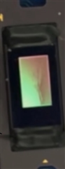
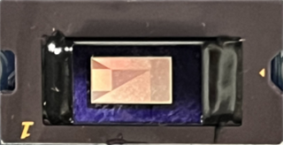
Display image of TI control board

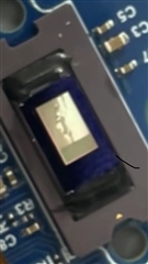
Our board displays images

  • Hello User,

    Which board did you remove the MSP430 from? Was it your design or was it removed for the EVM?

    In you photos, how are you able to ensure that the DMD is properly secured and that all data lanes to the DMD are properly aligned?

    Regards,

    John

  • Hi John,

    We made a new board modeled after TI EVM, and there was no MSP430 on this board.
    We didn't change anything else. Both boards use the DLP composer program provided by TI. I don't think it's a program problem, but I don't know what else could be causing this?

    Regards,

    Cherry

  • We thought the 430 had the same functionality as the computer, so we removed the 430 and only used the computer to interact with the FPGA. We think the FPGA can guarantee the data alignment. After I read the MSP430 program, I found that the FPGA1.0V, 1.8V, 3.3V power supply order is not the same. I would like to confirm whether there are timing requirements for the power supply of FPGA1.0V, 1.8V and 3.3V? We're powering up all three at the same time. Does this make a difference?

  • Hello Cherry,

    Our servers were down for the past two days. Our team is looking into these questions now and will get back to you next week. Thank you for your patience.

    Best,

    Maxine

  • Hi Maxine,

    The board we made shows the image missing the right quarter. We don't know whether the data sent by fpga is wrong, can you help us find the problem? Our hardware circuitry uses your files.

    Regards,

    Cherry

  • Hi Cherry,

    Please expect a reply from us by the end of the week.

    Regards,

    Austin

  • Hello Cherry,

    I think this might be the power-up order and sequence issue as you mentioned that you powering up 1.0V, 1.8V and 3.3V at the same time. It could trigger the Reset to the DMD. 

    Please refer to the FPGA Users guide and MSP430 code. I would recommend you to change the order and sequence of the power up rails. 

    Regards,

    Lori