This thread has been locked.

If you have a related question, please click the "Ask a related question" button in the top right corner. The newly created question will be automatically linked to this question.

DLP651NE: DMD

Part Number: DLP651NE
Other Parts Discussed in Thread: DLP3030-Q1, DLP5534-Q1, DLP9000

Hello

  • What is the fill factor for DLP651NE not reported in data sheet
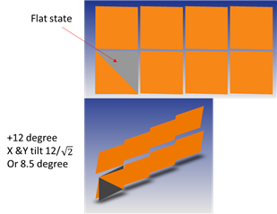
  • Can someone explain how could possibly the on-state ray tracing of mirrors, considering100% reflective lead to fill factor above even 89%. read this application form: https://www.ti.com/lit/ds/symlink/dlp9000.pdf?ts=1694427507345&ref_url=https%253A%252F%252Fwww.ti.com%252Fproduct%252FDLP9000  page 31 and application note: https://www.ti.com/lit/an/dlpa083b/dlpa083b.pdf?ts=1694384680206&ref_url=https%253A%252F%252Fwww.google.com%252F page 2 for onstate fill factor.  I am using zemax.  this is to adjust the gap between mirrors to get the proper fill factor. or someone please share the gap between the micro mirror arrays in flat state. no matter what you do the fill factor do not go above 90%. the only way to get fill factors of above 90% si to have mirror flat facing incident beam and then adjust the gap to get to whatever fill factor Ti reports. not to mention TI reports for example open etime 94% and one time 90% for DLP 9000. It is a mess in reporting correct values.  
  • what is the thickness of glass used in DLP651NE
  • what is the distance of back of glass to top of mirror arrays
  • can someone explain how could possibly the on-state 

Thank you whoever response to this

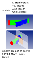
  • Ok this is how you go to get the fill factor: do on-state and adjust the gap and size to get same pitch  but put micromirrors at +12 degree and incident beam at 24 degree as follows:

  • Hello Babak,

    Thank you for reaching out on E2E, we are working with the team to answer your questions.

    Best,

    Aaron

  • Guys any update? Appreciate any input.

  • Hi Aaron... Kind follow up. Any update on answer to my questions. Appreciate your input. I am waiting for answer for my questions above

  • Hello Babak,

    After discussing with the members of the team, here is what is found:

    • Q. What is the fill factor for DLP651NE not reported in data sheet
      • A. I have noted that this is not on the DLP651NE data sheet - this will need to be updated. A quick look at the Application Note DMD Optical Efficiency for Visible Wavelengths shows comparable DMDs, such as DLP3030-Q1 or DLP5534-Q1 - which have a pitch of of 7.6um, 12 degrees of tilt and an illumination f-number of 2.4 - to have a fill factor of 94%.
    • Q. Can someone explain how could possibly the on-state ray tracing of mirrors, considering 100% reflective lead to fill factor above even 89%?
      • A. The mirror gap is 0.50um. The fill factor reported is a function of the optical illumination conditions. Since this is a 12 degree part, the fill factor is estimated based on a 2x tilt illumination angle = 24 degrees and a corresponding F/2.4 light cone. Your method in Zemax is correct, the fill factor is an on-state fill factor not when mirrors are flat. Thank you for finding inconsistency, we will take note to modify the value on the DLP9000 data sheet.
    • Q. What is the thickness of glass used in DLP651NE?
      • A. The glass is 1.1mm thick. Attached is a mechanical ICD file of this package. This can also be found under the DLP651NE 'Design & development' section of the product page under the CAD/CAE symbols tab.
    • Q. What is the distance of back of glass to top of mirror arrays?
      • The distance is 0.505mm. Please see attached mechanical ICD file.
    • Q. Can someone explain how could possibly the on-state...?
      • A. I think this is a repeat of the 2nd question. Please advise if this is not the case.

    I hope this was helpful!

    Best,

    Aaron

    ICD_s450-FYP-Package.pdf

  • Hi Aaron,
    Thank you for your responses. You answered all my questions. Except there is discrepancy between size 0.5um gap in flat-state and fill factor of 94% considering 7.6um pitch, 100% mirror reflectivity and on-state scenario. With this arrangement, I will get %93.377 ~%93.4 and not 94% accuracy. I am kindly being such a stickler as the gap size is effective in diffraction modeling losses for us. We are aware of tolerance +/-1 degree on mirror tilt. But that does not affect the tolerance in fill factor or gap.

    - Could you please either discuss with your colleges the 94% accuracy tolerance or, confirm the 0.5um gap. Please do not close the case as I will be using a 7000X microscope to measure the gap directly to verify. I trust your input on 0.5um or what you re-find/re-confirm on exact size of the gap. I will be going to verify this by next Thursday.

    - Additionally we want to know what the size of pivot hole in middle of mirror is. We need to model it to see how much light we are losing. 
    - Is middle pivot hole being all scattered/lost light? Thanks for answering this last question too.

    Thank you.

    Babak

  • Hello Babak,

    We utilize 26 degrees in our modeling and this is why we show a 94% fill factor. The calculations of fill factor will rarely match exactly with the actual performance of your system, each part has many variables that cannot be controlled in production. This can already be seen in the +/- 1 degree tilt angle.

    You can measure the gap visually if you would like. 

    I will have to go back with the team to confirm the pivot hole size.

    Best,

    Aaron

  • Thank you, Aaron,
    I understand.
    Thanks for asking about the pivot hole
    Could you please also find out the micro mirror thicknesses as I am modeling diffraction pattern using zemax Lumerical software. If you can guess the reflectivity of micromirror sides (top is known), I appreciate it too. 
    then we can close this case.
    thanks
    Babak

  • Hello Babak,

    Could you please advise the extent of the effort of modeling?

    The reflectivity of the micromirror sides is the same as the top, I will follow up with the team about the others.

    Best,

    Aaron

  • Thank you for reflectivity....
    I will be doing a full diffraction model using Lumerical connected to zemax. We are losing lots of power out of DMD and we must find out why. It is not a matter of efficiency for us. It is a matter of heat management in a small compartment which leads to mechanical tolerance swing and light loss at target.
    knowing the thickness helps. The pivot hole can help or be adjusted as % reflection from surface. We are so close to plug these realistic dimensions into my model and go from there. I guessed thickness to be half the gap based on my optical microscope and SEM photos of DMD floating on web googling it. but I prefer to have correct numbers than guess and estimate. Thanks so much for all your support. I appreciate it. 
    Babak

  • Hello Babak,

    The team would like to take this discussion off of the public forum here and hold a quick meeting with you. Our members have experience with this modeling strategy and we'd like to understand more how to help.

    Thank you for the questions!

    Aaron

  • Ok you have my cell and email... Please kindly call me or email me let's discuss this and we move forward. Thanks, Babak