This thread has been locked.

If you have a related question, please click the "Ask a related question" button in the top right corner. The newly created question will be automatically linked to this question.

DLP Link Signal positioning.

Hello,

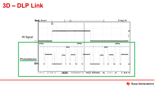
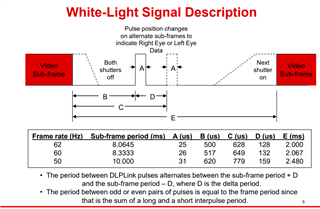
We are working on the DLP projectors and so I started studying the DLP protocol. I got the concept of the DLP Link Signal position before the respective Left/Right video sub frame in order to convert DLP glasses Left/Right sides transparent/opaque. 

I also went through the below mentioned forum for better understanding. 

https://e2e.ti.com/support/dlp-products-group/dlp/f/dlp-products-forum/1185910/dlp-link-protocol/4473575#4473575

I understood that the Dark Time Value varies with respect to projector manufacturers, BUT do the position of the DLP Link Signal(Light Pulse) for the Left and Right video subframes also vary ? Or they just remains the same irrespective of the projector brand? 


Thanks,
Dhruvil 

  • Hello Dhruvil,

    Thank you for your question, I have asked one of my colleagues to look into answering this. You should receive a response in the next day.

    Thank you for your patience.

    Best regards,
    Tristan Bottone

  • Hello Tristan,

    Any updates ?


    Thanks,
    Dhruvil

  • Hello, 

    Also, as mentioned in the dlp_link_3d_glasses_nonNDA pdf, the signals of Photodetector are given, So from where to obtain these signals, are they taken from the DLP Active shutter glasses or from any other way ? 


    Thanks,
    Dhruvil

  • Hello 

    Our colleague will be able to reach out by Tuesday to help you further with your query!

    I am sorry for the delay. 

    Best,

    Tristan Bottone

  • Hello, 

    We are waiting for your response. It would be great if you can reply before the end of the day.

    Thanks, 
    Dhruvil Patel 

  • I am re-assigning this ticket to someone who can help.

    The signals above are measured from the projector and the IR signal.  These are from the projector. 

    Jason

  • Hi Jason,

    DLP projector is sending white light data from the DMD device so can you let us how we can capture DLP white light data through our photo- diode because we are not seeing this signal on photo diode.

    Here is the graph of output of photo diode after amplifying it. This graph is taken in dark room to avoid any interference of the ambient light. In the graph below we notice a small spike with every 3 large spikes. We are not sure if that should be the behaviour.

    We want to detect the DLP signal on our device so we can figure out the status of the projector whether it is in 2D or 3D. We do not have any access to projector for debug/waveform capture.

    Thank You,

    Yamini

  • Dhruvil,

    For measuring the light output with an oscilloscope, we use a fairly simple circuit.  We typically use an Advanced Photonix PDB-C140; but we have used other photo-conductive PIN photo diodes as well.  We simply connect this to an oscilloscope with a high-impedance input (not 50-ohms).  We have also used commercial products that are built for this; but they tend to be quite expensive.

    What you are showing looks like pulses every ~8ms.  I think this is what one would expect to see with a 120Hz (60Hz eye pairs) 3D input (clarification - assuming the input data is black). If you measure the individual pulses, they should be approximately 26us wide; the spacing between adjacent pairs should vary by ~ 132us. 

    The data after the short spacing should be Left-eye; the data after the longer spacing should be right-eye, although that could be inverted depending on a number of things (so l/r need to be able to be swapped somewhere in case it is not matched).

    Keep in mind, the DLP-Link(tm) pulses will only be there if the project solution was built to support DLP Link and the projector is in one of those modes.  If the projector was not built with DLP-Link support, then the pulses will not be there.  Also keep in mind that the dark time (E in the diagram) is determined by the projector manufacturer at build time.  A proje1ctor may support a single dark time, or it might have configurations for different dark times for different 3D solutions.  It may have 3D modes with and without DLP-Link as well.

    Regards,

    Gary

  • Yamini,

    It seems likely that there is an issue with the photodiode or circuit.  The DLP projector is outputting R, G, B, pulses of light sequentially similar to what is shown above.  It is fundamentally how DLP projector works.  What type of photodiode are you using?  In our lab, we use often use the PDC140

    The circuit we use is shown here.  This is just for a lab use that we can plug into an o-scope.

    Please try to get the signal from the photodiode something similar to what is above as a starting point.

    Thanks,

    Jason

  • Hi,

    Thank you for response.

    We have used a circuit that you provided and taken the waveform again.The input data is in green colour with some 3D content.

    We have measured the individual pulses, they are approximately ~37us wide , not 26us; the spacing between adjacent pairs is vary by ~ 0.26ms. 

    Here is the graph and circuit that we used.

    The previous graph that i send had a black background and we are using SPDI752 photodiode.

    Thank You,

    Dhruvil

  • Those should be the DLP-Link(tm) pulses. 

  • Hi,

    Thank you for your help

    Can you let me know why I don't see the single shown in the pdf as I am not getting the 26us value on individual pulses and the spacing between adjacent pairs is not ~ 132us.

    Thank You,

    Dhruvil

  • The PDF you are referring to is from general documentation on how DLP-Link(tm) works; it is not a specification for implementation.  The tables are not limits, they are typical values.

    For the purposes of pulse detection: 

    • The Link pulse width (A) min/max is ~ 24-40us. 
    • The Pulse leading dark time minimum (B) is 400us (dark before the pulse). 
    • The Pulse trailing dark time minimum (= E-A-B) is specified as 1000us.  The tools used by projector developers will allow smaller dark times, which will decrease this value.  If they have a 3D solution that can switch faster than ~1800us, this time could theoretically be smaller; I don't know if anyone has done that.

    For the purposes of determine left/right eye, the gap time between detected pulses is used. 

    • The shorter gap occurs before the left eye data; the longer gap occurs before the right-eye data. 
    • (TLong - TShort) should vary between approximately 120us and 180us.