Hi Team,
We have again referred the PDF file that team sent earlier on last thread (https://e2e.ti.com/support/dlp-products-group/dlp/f/dlp-products-forum/1185910/dlp-link-protocol/4481017?tisearch=e2e-sitesearch&keymatch=%20user%3A416057#4481017) and we are trying to capture the graphs on photo diode (at P1.1 after the amplifier on TPS65835) and shutter glass but we are not able to capture the same signal as mentioned in PDF.
I have some questions/doubts regarding DLP link that i mentioned in below.
1) To enable the glasses, DLP projector is sending the white light data every frame but we are not seeing the DLP link signal.
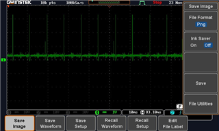
Here is the graphs of output of photo diode after amplify it. All these graphs are taken in dark room to avoid any interference of the ambient light. In the graph below we notice a small spike with every 3 large spikes. We are not sure if that should be the behaviour.

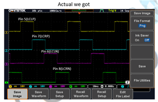
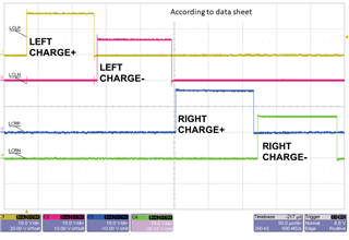
2) Here is the graphs of shutter glass (output of TPS65835). We are not getting the on-off sequence of right left glass as per datasheet.


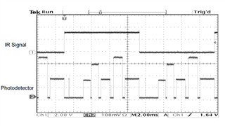
3) as mentioned in the dlp_link_3d_glasses_nonNDA.pdf,The detection of left and right frame are depend on IR Signal so how we can capture graphs of the IR signal and photo detector?

Our first objective is the clearly detect the DLP link signal and then work on our logic/conditions based on the DLP Link signal. As per the DLP link protocol, there is a small period between frames where both shutters are off and at that time DLP link signal appears but we are not able to distinguish the signal on the scope.
Let us know how we can get the correct signals.
Thank You,
Yamini


