This thread has been locked.

If you have a related question, please click the "Ask a related question" button in the top right corner. The newly created question will be automatically linked to this question.

DLPLCR65EVM: The evaluation module broke down

Part Number: DLPLCR65EVM
Other Parts Discussed in Thread: DLPC900, DLP9000

Dear Sir/Madam,

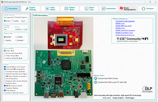
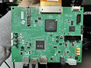
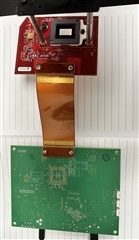
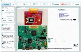
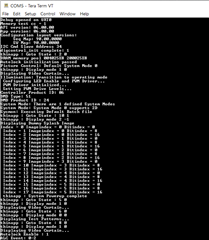
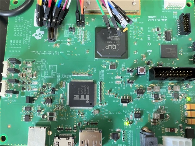
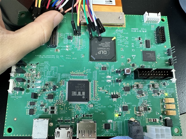
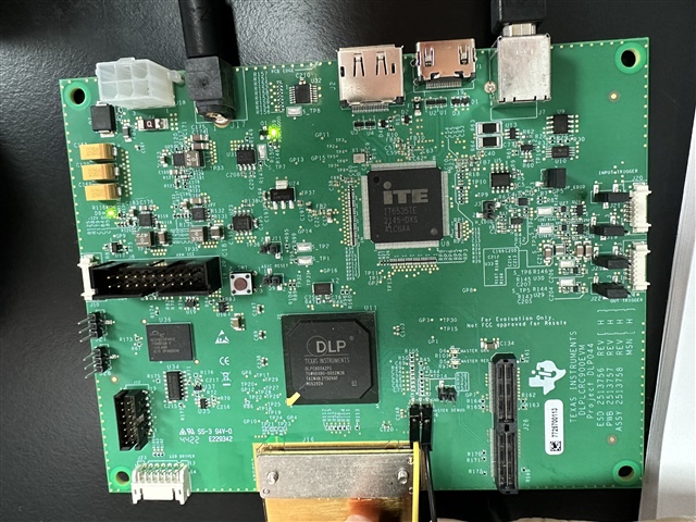
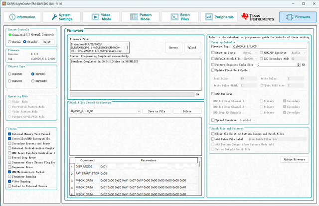
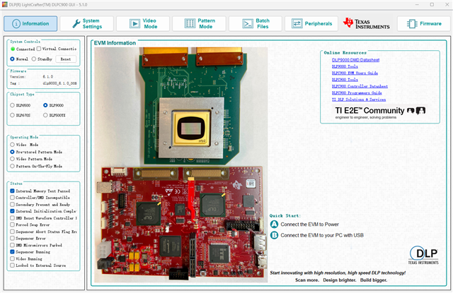
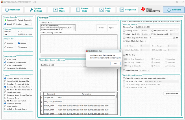
We bought an evaluation module (DLPLCR65EVM), the order is T04461630. Unfortunately, it suddenly broke down today when I used it. The GUI shows that the system is connected, but I can't use any operating mode, whatever mode I chose except the Video mode, it switched to Video mode. However, when I set the internal test pattern, there was no pattern shown on the DMD chip. Could you please evaluate this problem? Here are two pictures of the system which you may need. Feel free to ask me If there are any questions.

  • Hello Zhangyuzhen,

    Thank you for reaching out to us. I have a few questions and suggestions.

    1. Have you been using the EVM previously? Or did this happen right after purchasing it?
      May I ask what operations you were performing before the EVM stopped responding? Or was it at startup?

    2. I see that the DMD is in parked state from the "Status" information.
      Have you tried power-cycle or moving the system to Standby, wait for 2 mins, go to Normal mode?

    3. Please capture UART debug logs (see instructions below). This will help us narrow down the cause of failure.

      Debug messages from the FW can be routed through UART output connector (J6 on the Single DLPC900 EVM). You can use any serial emulator like Teraterm to capture these debug prints. 
      Example:

      Connection settings:

    Thank you,

    Regards,
    Aishwarya

  • Hi Aishwarya,

    Thanks for your quick reply.

    1. Yes I have been using the EVM for two months. I think I didn't do something special before the EVM stopped responding, I did some repetitive operations as usual, it happened when I tried to start a new cycle experiment.

    2. Yes  I tried power-cycle and Standby several times, but there is nothing changed.

    3. I haven't measured UART with output connectors before, I searched some connectors online, but I'm not sure which one is the correct one. could you point out it for me? if they are all wrong, could you show me a correct one?

    Thank you so much.

    Cheers,

    Yuzhen

  • Hello Zhangyuzhen,

    We use a general Serial-to-USB cable such as TTL-234X-5V.

    Driver might be required - https://ftdichip.com/wp-content/uploads/2021/08/CDM212364_Setup.zip

    Thank you,

    Aishwarya

  • Hi Aishwarya,

    I bought TTL-234X-5V, but I found that the voltage of the J6 module is 3.3V?

    BTW, our guarantee date is very near, I am worried that it will expire after I test and capture UART debug logs...

    Best wishes,

    Yuzhen

  • Hello Yuzhen,

    The cable that you have purchased should be alright. Please connect TX out (Pin2 on J6) to Yellow and GND (Pin6 on J6) to Black.

    Do not worry about the warranty. You have 90 days from the purchase date to first issue report date (Nov 24th, 2023).

    Thank you,

    With Regards,
    Aishwarya

  • Hi Aishwarya,

    I connected Pin2 to yellow (and orange because the cable datasheet shows that the orange corresponds to TXD output), Pin6 to blank, and Pin 1 to red, and I connected the EVM with its USB and power (when the power on, if the Pin1 to red disconnecting, the DLP shows connected. If the Pin1 to red connecting, the DLP shows disconnected). but the Tera term shows nothing. could you tell me if there is something wrong?

    Thanks a lot!

    Yuzhen

  • Yuzhen,

    I would recommend to just connect as follows:

    1. Pin 2 on J6 (TX out from DLPC900) to Pin 5 on cable connector (Yellow, RXD)
    2. Pin 6 on J6 (GND) to Pin 1 on cable connector (Black, GND)


    3. Please install the FTDI drivers. This is what the Teraterm should show when it recognizes the Serial-to-USB cable:

    Thank you,

    Regards,
    Aishwarya

  • Hi Aishwarya, 

    I did as you recommended. but the Tera term still shows nothing? should I type something or click sth?

    Thanks again.

    Yuzhen

  • Hello Yuhzen,

    I am Aishwarya's colleague.  Have you tried reprogramming the firmware using the boothold jumper as outlined in the User Guide DLPU101C in section 7.9.2 Reprogram Firmware for a Different Supported DMD on page 53.  This can be used to also reprogram the default firmware for the same device if it has become corrupted somehow.

    This is also spelled out in a note in section 7.11 JTAG Flash Programming on page 55.

    The status flag Controller/DMD incompatible shows that the controller is not recognizing the DMD.  This could have multiple causes.  The debug output should tell you where it is going wrong.

    Does either board get hotter than expected.  Also do you have a second 6500 system?  If so you can try carefully putting the DMD from the second into the ZIF socket of the non-working one to see if it then works.  If so, this means the DMD has somehow become damaged.

    I recommend making a mount system that minimizes contact with the board during operation.  We often mount long standoff's in the four corner holes.

    Give the reprogram procedure a try and let us know the results.

    Fizix

  • Hi Fizix,

    Thanks for your reply.

    Please understand that I'm not an electronics engineer, I don't know where can I install the BOOTHold jumper, I even don't know what it is. These operations wasted some of my time, so I suggested that we make an online meeting to find out the problem efficiently, or if I can deliver this board to the TI engineer in China to let them find out the problem?

    Thanks a lot.

    Yuzhen

  • Hello Yuzhen,

    Are you already in touch with a TI engineer in China?

    In the meantime, here is a link to the DLP® LightCrafterTm Single DLPC900 Evaluation Module (EVM) User's Guide.

    The reprogram procedure should not take more than 15 minutes.  The location of the boothold jumper is shown on page 9 (labeled J11).

    Fizix

    P.S.  You only need the GUI software, the EVM with the boothold jumper installed, powered up and connected via USB.  No other hardware is needed for this simple test.

  • Hi Fizix,

    What is the boot hold jumper, can you show me a picture?  It sounds like hardware because the first step tells me to place the boot hold jumper onto the EVM.

    I haven't communicated with a TI engineer in China.

    Thanks a lot.

  • Hi, did I finish the reprogramming? what should I do for the next step?

  • Hello again Yuzhen,

    If the image you have of the GUI is from after the reprogramming, then it is very unlikely that it was just a corrupted firmware.

    Typically this indicates that the DMD has become electrically damaged in some way (the flag "Controller/DMD Incompatible").  The TI China offices (engineers) are not set up to receive kits in the manner you are suggesting.

    You should start a return request for replacement.  You can point to this thread as the date it was first reported.

    Fizix

  • Hi again Fizix,

    Thanks for the instruction and evaluation! It helps a lot!

    Yuzhen

  • Sorry to bother you again Fizix,

    I received the new DLP6500BFYE, but when I powered it on, the GUI showed the chipset type as DLP9000 (see picture), I manually chose DLP6500 and set an internal test pattern, the DMD projected nothing, but I can feel that the DMD was heating up. I tried updating the firmware, but it was reported as the second picture (my DLP6500.img file is under the DLP9000 folder). Could you please tell me how to solve this problem? Thanks a lot!

    Yuzhen

  • Hello again Yuzhen,

    Since it seems to be programmed with the wrong FW, you will have to install the BootHold jumper in order to program it with the 6500 FW and then remove the jumper.

    Please let me know if you have trouble programming it.  You will manually have to select 6500 on the radio buttons on the left status strip, otherwise it will not let you select the single controller image file.

    Fizix

  • Hi Fizix, 

    Unfortunately, I tried reprogramming, but after that, when I powered it on again, the GUI showed it was on a "standby" state,  I clicked the "Normal button", it jumped to "Standby" again.

    Yuzhen

  • Hello again Yuzhen,

    I am replying on behalf of Fizix.

    Please try the following:

    1. Install the boothold jumper (J11 on the DLPC900 EVM). Power on the EVM.
    2. In the GUI, manually select the DLP6500 in 'Chipset Type'.
    3. Go to the 'Firmware' page. Click on 'Browse'.
    4. Go to 'DLPR900PROM' installation directory. Navigate to the dlp6500 firmware image folder.
      Default location - "C:\Texas Instruments-DLP\DLPR900PROM-6.1.0\DLPR900PROM-6.1.0\DLPR900PROM-6500-v6.1.0
    5. Delete the folder named 'FlashLoaderCache', if present.
    6. Program the 'dlp6500_6.2.0_OOB.img' firmware image.
    7. After programming is completed, power off the EVM and uninstall the jumper.

    Let me know if this works.

    Thank you,

    Aishwarya

  • Hi Aishwarya,

    I tried programming again, but it kept a "standby" state ...

    Yuzhen

  • At least, the GUI recognizes the DLP6500 DMD now.

    Few questions:

    1. Do you see the heartbeat LED (D6) on DLPC900?
    2. Are you able to capture the UART debug logs now?
    3. Also, just for confirmation, have you removed the J11 jumper?

    Thanks,
    Aishwarya

  • 1. No the D6 didn't blink.

    2. Unluckily no... it only identified one port, port7.

    3.Yes I removed.

    Yuzhen

  • Yuzhen,

    That is unfortunate.

    1. From your previous posts, it seems that the USB communication is established. The UART debug initialization happens before the USB communication opens. Is COM7 the port where you have connected the serial cable? Please check the 'Device Managers' to identify which port it is.
    2. Try reprogramming(use the exact steps as given in the previous post) with the DMD disconnected. Is the heartbeat LED still off? Do you see the fault status LED blinking?

    Thank you,
    Aishwarya

  • Hi 

    1. Yes I checked out that the the serial cable is COM7. do I need to send some instruction on teraterm to receive the log?

    2. I reprogrammed again, the D6 was still off.

    Yuzhen

  • Hello Yuzhen,

    We require the UART debug logs to debug the issue. We can try all our experiments without DMD connected. 

    Let us discuss this directly over email. We can also set up a conference call, if required.

    Thank you,
    Aishwarya