This thread has been locked.

If you have a related question, please click the "Ask a related question" button in the top right corner. The newly created question will be automatically linked to this question.

DLP670S Inverse Pattern Display Issue - GUI project map

Other Parts Discussed in Thread: DLP670S

Hi,sir/miss,

     I am optical engineer of metacam.tech from Beijing.  We bought DLP670S from TI.We meet some questions to answer,the questions are:

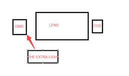
     We start the GUI to project. Sometimes,we find the project map is mistake.Figure 1 is the orginal picture.Figure 2 is the mistake picture.The black an white area is reverse.


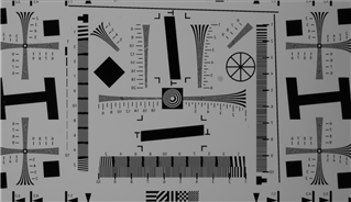
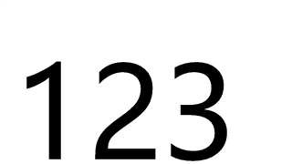
            Figure1 orginal picture


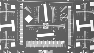
                Figure2 mistake picture

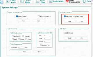
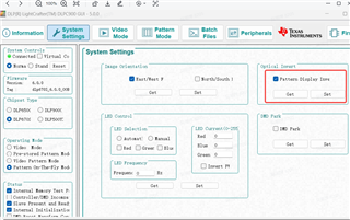
   If we use the system setting ,choose Patter  display inverse,sometimes we can get the correct picture,but sometimes ,we can't get the correct one.

Questions:1.Why we get the mistake picture?

                 2.How we get the correct picture when the picture project is mistake?

We are waiting for your receive.Thank you.

Best wishes.

Liping Wu 

  • I am not an expert on this particular product… my first thought is that you may be illuminating the DMD from the corner (off state direction) instead of the bottom.  Which side are you illuminating the DMD from?

    Regards,

    Gary

  • Hello Liping,

    I want to make sure that I am understanding correctly what you are seeing.  Here is what I am understanding:

    If you start the system up and put the pattern in the Pattern Design tab of the Pattern-on-the-Fly Mode window and then load it, that sometimes it is correct and sometimes inverted.  Please confirm that nothing else is changing in between.  You are not changing illumination angle or anything else mechanically.

    Are you power cycling the EVM board?  If the invert bit get set and the board remains on, it will remain set until it is either cleared by clearing the checkmark and hitting "Set" or by power cycling the EVM.  Simply restarting the PC side software (GUI) does not clear the invert bit.  Therefore if the Invert bit is set and you restart just the GUI, the next loaded image will be still be inverted.  If you then go and "Set" invert again it will still be set.  The only way to be sure the invert bit is cleared is to set it "on" using "Set" and then clear it using "Set".

    Fizix

  • Thanks Gary S for your reply.We directly use the camera to collect the DMD chip projection,using the extra source.So the image is not about the illuminate angle.The layout is blow.

  • Hello Fizix,

        I am happy to receive your reply.

        Your understand is correct.We use the correct controls.We start the system up and put the pattern in the Pattern Design tab of the Pattern-on-the-Fly Mode window and then load it ,and not changing illumination angle or anything else mechanically.Just change the project map.Then we get the mistask map.

        The EVM board is power cycling.I understand your setting and we will set as you said.

        Thank you very much.

        Best wishes.

  • Hello again Liping,

    Are you still experiencing the issue?  We have not seen spontaneous "negative" images before.  I am not sure what to advise you further.

    If this has answered your question please accept this answer.  If not, reject it and lets get more information so we can attempt to help you solve it.

    Fizix

  • Hello Fizix,

         I am sorry too late to reply you.

         I am experiencing what you suggest .When we get a mistake picture, first,we restart the GUI,but the picture is mistake.Sencond,we turn off PCB power and restart the GUI,the picture is mistake too.Third we restart GUI,and choose optical invert we get the correct picture.When we get the correct picture,we can cancel the optical invert,still get the correct one until next accident.

          Please help us to solve the problem.We get the mistake picture random,can't find the rule.

          We are waiting for you reply,thanks.

           Best wishes

  • Hi Liping,

    Thanks for sending us your testing procedure for this. Fizix is out of the office until January 3rd if you can wait until the end of the first week of January or early the second week.

    Thank you for your patience,
    Michael Ly

  • Hello again Liping,

    I am not sure how to proceed.  When I get back to the office on Jan 3rd, I will see if I can replicate the issue, but since you indicate the extra light source is not moving or being moved, to my knowledge we have never seen random inverting data as you describe.

    I am also going to send you a friend invite in case we need to connect via a conference call.

    Fizix

  • Hi Fizix,

        Thanks for your letter.

        Thank you for sending me the friend invite.We wil have message via the conference call.

        We will experience later.Thanks for your reply.

  • I will start a conversation in the private message area.

  • Hello Fizix,

          Thanks for your reply.

          Today I have done the experience again,and I find the rule.


                                          figure 1   

                                                                                                              figure 2


                                     figure 3                      

                                                                                                                 figure4

         When I turn on the PCB power and start the GUI, set the figure 1 under the pattern modle.

         First,I get a reverse pic,as figure 2(figure 2 is photoed by CMOS sensor,please neglect the incomplete image just the FOV not matching between CMOS sensor and DMD).

         Figure 2 is photoed by telephone direct from DMD. 

         Sencond,choose the optical invert,update LUT,update is important,get the correct pic,as figure 4.

         I have done the experience three times,and make sure this process is no problem.

         I think we must choose the optical invert as get the correct picture.Maybe we neglect update LUT at the previous experience.

         But I have the problem is :why we need open the optical invert to get the correct one?

          Thanks for your reply.

  • Hello again Liping,

    Looking closely at your image of the DMD (Figure 2)n it appears that you are illuminating from the lower left corner of the DMD.

    In your picture the DMD needs to be illuminated directly from the direction of the bottom of the DMD at an angle 35 degrees from the array normal.

    What you see is very much related to the direction of the incoming light and the point of observation.  I think then you will see it as black letters on a white background without turning on "Optical Invert".

    Please let me know if this does not help.

    Fizix

  • Hello again Liping,

    I am sorry, I forgot momentarily that this DMD is bottom illuminated.  See my edits to the answer in blue.

    Fizix

  • Hello Fizix,

         Thanks for your replying.

         Maybe I will experience it after three months,as the product needs times to make.Then I will give you the result.


  • Hello Liping,

    Please mark this thread as answered for now and open a new inquiry if needed at that time.  You can put a link back to this thread. for context.  THANKS!

    Fizix

  • Hello Fizix,

         Thanks for your remind,I have marked.

  • Hello Liping,

    Thank you!  Please let me know once you have the product.  You can send me a private message if you like.  

    Fizix

  • Hello Fizix,

          I will send you private message if I can find the place.

          THANKS.

  • Hello Liping,

    You can reply to the private message that I sent you.  That is the place.

    Fizix