This thread has been locked.

If you have a related question, please click the "Ask a related question" button in the top right corner. The newly created question will be automatically linked to this question.

DLPC910: DLPC910 Design

Part Number: DLPC910

Hello,

      I am currently designing the DLPC910 platform and have two questions.

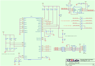
     1. Due to the discontinuation of DLPR chips, the DLPC910 currently uses SPI FLASH as the configuration device. The schematic diagram I designed is shown below. Please help me check if there are any issues.
      

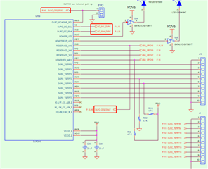
    2. In DLPC910EVM, there are many TSTP signals, but in practical applications, these signals are not needed. In the following figure, can all signals except for those marked in red be omitted, that is, the pins are floating.
     

   Thanks!

   Sunny

  • Hi again Sunny,

    I can take a look at the first picture and give an answer some time before the end of this week. One thing I can say for now is to make sure the SPI PROM you are using is compatible with the Xilinx FPGA on the DLPC910.

    As for the second picture, I will need to ask my coworker who gets back on January 3rd. He may know more about this, as there may be some test points that are not recommended to remove.

    Regards,
    Michael Ly

  • Hi Sunny,

    1. I took a look at the first schematic you posted above, and would like to know the part number of your JTAG header. I tried to look it up based off what I assume is "SIP6-100," but I am unable to find this part. Is this custom?
    The original header we have is intended for use with the Digilent JTAG-HS2 programmer, which is intended for high-speed data.
    P
    lease allow more time for me to expand on the resistive network and external protection you have added between the connector.

    2. According to the user guide, the DLPC_TSTPT 8 through 15 are reserved for TI internal use. I do not see an issue removing this, but please allow me to consult my coworker when he is back tomorrow afternoon in case these end up being useful to you. I will also ask him more about the USB GPIOs, but the signals circled on your image appear correct. You will certainly need those.

    Regards,
    Michael Ly

  • Hi Sunny,

    I just finished talking with my coworker about this. We both think that you can remove the test points DLPC_TSTPT 0 through 15, as they are all TI Internal test points. However, I do think it is useful to have the extra ground points around the board if you want to replace these with hardware ground loops you can probe. This has proven useful in the past when debugging.
    Please also make sure that you are only making USB_GPIO15 floating and maintaining the connection to the DLPC_CONFIG_DOUT net.

    Please make sure that the SPI PROM you are using is compatible with the Xilinx Virtex V FPGA on the DLPC910 board or find a compatible chip if what you have is not compatible.

    Regards,
    Michael Ly