This thread has been locked.

If you have a related question, please click the "Ask a related question" button in the top right corner. The newly created question will be automatically linked to this question.

DLP2021LEQ1EVM: EVM not responding after Composer flashing error

Part Number: DLP2021LEQ1EVM
Other Parts Discussed in Thread: DLP3021LEQ1EVM

Hi,

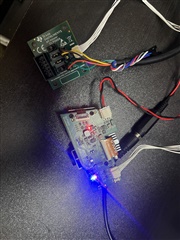
My EVM is not responding to both control program mode and fpga mode.

I am able to connect via GUI.

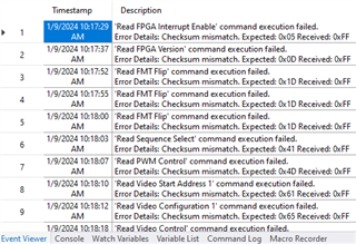
When i tried to change images via composer, it got crashed with below error:

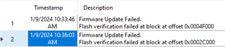
"Firmware update failed, flash verification failed at block at offset 0x00083000".

Even i tried to flash the default img, still same issue. Kindly help to fix this error.

Thank you

Kalaivani K

  • Hello Kalaivani,

    In the DLP2021LEQ1EVM User's Guide section 4.17, there are instructions for programming the EVM.

    Please make sure the EVM is in the Flash Programming operation mode and make sure you have the correct hardware connections between the FTDI USB-to-SPI cable and the SPI adapter board. 

    Below is the video training of the hardware setup for the DLP3021LEQ1EVM, but it's also useful for the DLP2021LEQ1EVM: https://www.ti.com/video/6276058638001

    Please let us know if you still have the issue after following these steps.

    Regards,

    Lori 

  • Hi Lori,

    I followed the instructions; the issue is still present. The EVM is not responding. 

    .

    Its not working in local host mode also after the crash. Kindly help to fix this issue.

    Thanks

    Kalaivani K

  • Hi Kalaivani,

    When you said that "The EVM is not responding", can you read/write any registers in the DLP Control Program? What the message is showed in the Command Log window? 

    What's the SPI clock rate  when you programming flash in the Flash programming mode through Composer? Please try to slow down the clock rate in the Connections Tab.

    Also, please try to only open either Control Program or Composer at a time when connecting with the EVM.

    Regards,

    Lori 

  • Hi Lori,

    The command log output is as below while running the script. 

    When I try to get the values from general tab below errors were seen.

    I tried reducing clock speed in composer(4.3MHz and 3MHz) still its failing. 

    Thanks

    Kalaivani K

  • Hi Kalaivani,

    When you running the script, what's the projected image displayed on the wall? It should be a "Bird" image based on your shared commands in the first screenshot.

    The checksum mismatch could be a result of a comm interface issue or if the FPGA is not in the host mute mode. Please turn off the supply power first, and set the operation mode switches to the Host Mute. Then, turn on the supply power, and read back command. 

    Were you able to see a racecar video being displayed when you first received the EVM and followed Section 2 Quick start instructions in the EVM User's guide?

    Regards,

    Lori 

  • Hi Lori,

    The Racecar video was displayed at first. Even i was able to change image with via control program. 

    When I tried to change via composer program it stopped working. 

    The DLP stopped working in both modes, no image or video is shown after that. 

    Thanks

    Kalaivani K

  • Hi Kalaivani,

    It's likely a SPI interface issue. Please use a logic analyzer/oscilloscope to probe on the SPI_CLK, SPI_CSZ, SPI_MOSI, and SPI_MISO signals, and check if you can get the proper waveforms. 

    If you have an extra FTDI cable, please try to replace.

    Regards,

    Lori 

  • Hi Lori,

    Good day.

    I tried changing the SPI cable, still same issue. Is there any other way to debug/reset the EVM?

    Thank you,

    Kalaivani K

  • Hi Kalaivani,

    Did you have a chance to probe on the SPI signals that I mentioned above? Have you seen the proper SPI waveforms?

    Regards,

    Lori 

  • Hi Lori,

    I could check the signals with a scope, as below:

    mosi                                                     clk                                               miso 

    Thanks

    Kalaivani K

  • Hi Kalaivani,

    It's hard to see if your CLK signal is pulled high and remain high or it's getting pulses. You may want to capture these signals on one screen. 

    Here is the SPI interface timing diagram from FPGA user's guide:

    In my opinion, you need to double check your SPI connections. As an alternative to FTDI USB-to-SPI cable, you can use Cheetah SPI Host adapter that is sold separately from Total Phase. 

    After ensuring that the SPI connection is correct, please try re-programming the EVM using the default flash image file and make sure to follow the instructions in the EVM User's guide. 

    Regards,

    Lori 

  • Hi Lori,

    I probed the SPI signals to oscilloscope to read the values, and found it was always high, the issue was with SPI connection as you said. I changed the cable with proper connections, now i am able to use the control program and composer flashing. its working fine. 

    Thank you for your support to resolve the issue.

    Could you please tell me if I can change the image/video display with external trigger (eg. ARM controller) in local host mode or Host Mute mode?

    Thank you,

    Kalaivani K

  • Hi Kalaivani,

    Thank you for confirming and I'm glad it's working now. 

    I may need more information about the external trigger you mentioned and the configuration of your design.

    For using the TI EVM, you can change the image/video display by using following commands in the Control Program and keep the EVM in local host mode. The Video start address is the video offset information that you can find in your composer project folder -> Build -> BuildLog.html -> video offset information.

    Regards,

    Lori 

  • Hi Lori, 

    Good Day.

    We would like to control the display using a NXP controller(S32KXX). We want to send SPI command from the controller to change the image/video which is already flashed via the composer program. 

    Could you kindly provide with the SPI configuration and format. 

    1. CLK Frequency

    2. CPOL, CPHA configuration

    3. CS or !CS

    4. 8bit/16bit/24bit/32bit?

    5. MSB /LSB first?

    6. is there any chip enable pin? 

    If there any documentation for these details would be helpful. 

    Thanks

    Kalaivani K

  • Hello Kalaivani,

    All the SPI interface details you need to know are mentioned in the DLP3021-Q1 FPGA User's Guide Section 3.3 Host SPI Interface Timing and Section 6 Host Command Protocol.

    You need to ensure your host controller is set in the SPI_MODE=0, the bit order is MSB first and the clock frequency is 5MHz or slower.

    For write command, ensure you are sending 8 bytes total {CMD, ADDR (LSB), ADDR (MSB), DATA3, DATA2, DATA1, DATA0, Checksum}. The checksum is calculated as a 8-bit checksum modulo 256. Please refer to figure 6 for write cmd and figure 7 for read cmd. 

    You can use DLP Control Program - Command log as an example when sending or reading SPI command.

    Regards,

    Lori 

  • Hi Lori,

    I tried sending a Command from NXP S32 controller, with below settings:

    Clock:5Mhz

    cp = active high, read on odd edge & transfer on falling edge.

    cs = active low

    data = {0x00,0x20,0x00,0x10,0x00,0x00,0x00,0x30} - flip command (format same as from control program console)

    Display is not changing, and I am getting 0xFF from the device. 

    Any other parameter to be configured to make it work, am I missing something?

    Thank you,

    Kalaivani K

  • Hello Kalavani,

    We will look into this and get back to oyu by middle of next week.

    regards,
    Vivek

  • Hi Kalaivani,

    Ensure the EVM switches are set to the "Host Mute" mode when attempting to send commands from your external NXP S32 controller.

    The 5MHz is valid.

    CPOL and CPHA must both be '0' (defined as Mode 0) where data is sampled at the leading rising edge of the clock. However, according to your description, you are sampling data on the "falling edge". I am not sure how the "odd edge" translates to the SPI Mode, but please check or change your SPI Mode. Since there are only four SPI modes, you can try all four.