Other Parts Discussed in Thread: SN65DSI83
I am calculating the openLDI timing for DLPC230-Q1, so two questions that:
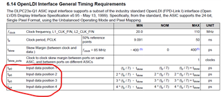
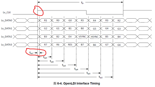
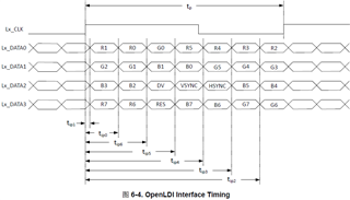
1. can we consider Tskew in DLPC30-Q1 datasheet(figure1) is Rsposn_min/max (figure2) mentioned in snla249.pdf?
2. does Tskew include input CLK cycle to cycle jitter?
thanks a lot!
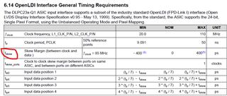
figure1
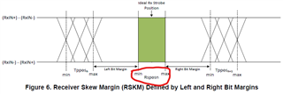
figure2