This thread has been locked.

If you have a related question, please click the "Ask a related question" button in the top right corner. The newly created question will be automatically linked to this question.

DLPLCRC900DEVM: Daughter board not communicating

Part Number: DLPLCRC900DEVM
Other Parts Discussed in Thread: DLP9000, DLP670S, , DLPC900

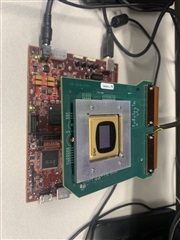
we are looking to move to the latest version of our exist DMD. as such we have the hardware below.

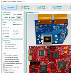
when we run LightCrafter it says the board is DLP670S not DLP9000 see below. and the board seems 'connected' but is unresponsive - can not enable video mode and no status reported.

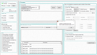
when we try to upload new firmware (master and slave), after saying YES to up dating the boot loader, we get the following error...

we are stuck and need this new DMD to work as a replacement for our old 9000 series 2560x1600 DMD is no long available!

any help greatly appreciated!

  • Hello Rex,

    Thank you for reaching out to us on E2E! I am reaching out to a team member who can help you more directly.

    Best,

    Aaron

  • Hi ,

    Thank you for the clear, detailed photos and screenshots!

    I see that your controller has the DLP670S v6.0.0 firmware on it.

    Let's try to do the following, as the DLPLCRC900DEVM expects a DLP670S based off the firmware loaded.

    1. Close all instances of the DLPC900 GUI software
    2. Power off your controller board and wait a few seconds for power to drain
    3. Install a jumper to short pins 1 and 2 of J12 - BOOTHOLDZ together
    4. Power on your EVM once again
    5. Start a new instance of the DLPC900 GUI -- the GUI will not recognize  the DMD attached
    6. Please select the correct DMD in the GUI using one of the radio buttons
    7. Go to the firmware tab of the GUI and upload the appropriate firmware for the DMD you intend to interface with
    8. Press the upload button to flash the controller
    9. Once the GUI finishes flashing and verifying the new  image, power down the controller and remove the J12 BOOTHOLDZ jumper -- you may place it back on just one of the pins for safe storage
    10. Power up the EVM again and reconnect to your GUI to see if your new DMD EVM is properly communicating

    If this resolves your issue, please let me know by clicking the, "This resolved my issue button." Else, let's dig into it deeper after we get more information.

    Best regards,
    Michael Ly

  • Hi Michael,

    ok sounds good will do shortly... a couple of beforehand questions:

    - the new DMD board and chip (see first image above) has NO visible model numbers! it is supposed to be the new DLP9000 replacement, so we use DLP9000, correct?

    - where / how can i download the very latest firmware from? is there a link?

    thx,

    rex

  • Hello Rex,

    You can download the latest FW (v6.2.0) and GUI (v5.2.0) versions from https://www.ti.com/tool/DLPR900 and https://www.ti.com/tool/DLPC900REF-SW.

    The part number for the DMD should be on the bottom side of the DMD:

    Thank you,

    With Regards,
    Aishwarya

  • thank you very much, this all seemed to fix it! got the mother board and DMD board burned to new dlp9000 firmware and it fired up great. we will be testing the unit in our instruments to make sure these new 9000 DMD and dlp900's are solid replacements for our old ones.

    in the meantime, i have a couple additional questions:

    - is there any way to upload our display image through the USB or I2C ports, we use 2560 x 1600 resolution?

    - we are finding some dead mirrors within a year, so we are looking at a couple of improvements:

         - can we add a small fan to increase the DMD cooling or do you recommend any other ideas?

         - most of our mirrors are 90% off during a run which can take 3-5 days. we are looking at using IDLE MODE and STANDBY MODE to try and restore the 50/50 duty cycle. which do you suggest? seems like IDLE restored the duty cycle better, but can we run it for extended times without hurting anything?

    thank you ahead of time for your help on this!

    rex

  • Hi Rex,

    I'm happy to hear Aishwarya and I were able to get your boards up and running!

    - is there any way to upload our display image through the USB or I2C ports, we use 2560 x 1600 resolution?

    You may upload your own patterns through the USB or through I2C. Please refer to the DLPLCRC900DEVM user manual linked here and the DLPC900 programmer's guide, also linked here.

    Section 3 of the user's guide takes you through how to interface with the DLPC900 GUI via USB while the programmer's guide gives a deeper look at how one would interface with the DLPC900 through its command set.

     - can we add a small fan to increase the DMD cooling or do you recommend any other ideas?

    I am unsure if you need it, but this would be a question for someone on the thermal team. However, we do have a heat sink over here in our labs at Texas Instruments. The boards can get a little warm after some use.

    I believe we should have mechanical step files of our DLPC900 EVMs out in the upcoming month or so. Please keep an eye out for this.

    most of our mirrors are 90% off during a run which can take 3-5 days. we are looking at using IDLE MODE and STANDBY MODE to try and restore the 50/50 duty cycle. which do you suggest?

    Let me talk to my colleague about this question, as I cannot remember which is the recommended option. STANDBY MODE is intended for use right before a power down of a system, though. Section 3.6.6's note does recommend using IDLE MODE as often as possible when not illuminating any patterns, however.

    Please give me a day or two to get back to you on this, Rex.

    Regards,
    Michael Ly

  • Hi Rex,

    May I get a bit more clarification on this?

    most of our mirrors are 90% off during a run which can take 3-5 days. we are looking at using IDLE MODE and STANDBY MODE to try and restore the 50/50 duty cycle. which do you suggest?

    I was reading this again to get input from my colleague, but I want to make sure what I am relaying to him is in fact what you are doing. What does, "most of our mirrors are 90% off during a run" mean?

    Are you saying that the you are not displaying anything for 90% of the time over 3-5 days? Or is it that 90% of the mirrors on the DMD are off, and pattern data is being sent during that time over 3-5 days?

    Regards,
    Michael Ly

  • Hi Michael,

    i tried sending the below once and it was bounced back. here is another try...

    good question, it's a little complicated... Here are more details...

    we synthesis polymer strands one molecule at a time. to do this we add one molecule at a time or per cycle. a total run may have 200 cycles. each cycle starts with an initial exposure (light) which uses the DMD for about 30 seconds. then a molecule is added and it must couple for 2-45 minutes. after that the next cycle is run. multiple builds are running simultaneously which makes predicting the time between exposures (when the DMD is needed) very difficult; it can vary between 1 and 45 minutes. 
    the DMD is running in video mode via HDMI as our second monitor. during an exposure we 'display' a unique mask (that varies for per exposure) for the duration of the exposure. then we currently blank the screen (and DMD) to all black until the next exposure. this makes the duty cycle of the mirrors quite lopsided, let's say 10/90 or on 10% and off 90%. we are investigating how to move this ratio to 50/50 using the IDLE mode instead of a black screen whenever we are not doing an exposure. over time, this will average our ratio toward 50/50.
    can we use the IDLE mode for so long between exposures? STANDBY mode looks better but it's requirement of ~2 minutes minimum duration time could interfere with our process timing under certain circumstances.
    our actual goal here is to run the DMDs more optimally and reduce our dead mirror rate!
    your thoughts greatly appreciated!
    rex
  • Hi Mechael,

    in reference to this answer:

    - is there any way to upload our display image through the USB or I2C ports, we use 2560 x 1600 resolution?

    You may upload your own patterns through the USB or through I2C. Please refer to the DLPLCRC900DEVM user manual linked here and the DLPC900 programmer's guide, also linked here.

    i was aware of this but was under the impression that pattern size was restricted. our images are 2560 x 1600 resolution which makes for a large image / pattern, are you saying this size is possible via USB? and since we need to do this quickly, how long might a USB transfer of such a file size take?

    thank you,

    rex

  • Rex,

    I think I've had enough time to digest how this works, but there are still some additional questions I want to ask.

    I've sent you a friend request on E2E so we can take this offline and maybe take a voice call together. I think this would be the best way to figuring out next steps.

    Regards,
    Michael Ly

  • Hi Rex,

    I am going to mark this thread as resolved, but you may open the thread back up within 14 days' time.

    Per our call a month ago, we discussed that uploading patterns via USB or I2C might be too slow for your application, thus the video mode may be preferred in your application.

    We also discussed what 50/50 meant and what we can do to exercise the mirrors to avoid stuck pixels/mirrors. I want to apologize and say that I was wrong on how 50/50 works. I previously said something to this effect: Displaying one pattern for 5 hours and then displaying the complement for another 5 hours might not be good enough for a 50/50. This is not true. If you know what patterns you are using, you can, in fact, do this to get to a closer 50/50 duty cycle!

    On top of that, we discussed that IDLE mode may be best for your application between exposure times. If we cannot guarantee a non-exposed time of 2 minutes, we should not use STANDBY mode. If we can guarantee a non-exposure time of over 2 minutes, then STANDBY should be used.

    Please also note that, during the time you do not wish to display a mask for your application, that you should turn off your illumination source. You should not be keeping your illumination source on with the mirrors in the "OFF" state, as the DMD is a bistable device. It has two states: OFF and ON.

    By sending a command to the DMD that says, "set all rows to OFF," you are still setting the mirrors in one of its two states. This can cause stuck pixels if there is a very lopsided duty cycle. There is technically a third "flat state" where the micromirrors do not receive electrical bias to pull it to one side or the other (OFF/ON). This third state is what the STANDBY mode aims for. By sending a 50/50 duty cycle to the micromirrors and exercising them, the standby mode will, after 2 minutes, make it so that the micromirrors are nominally flat, allowing you to safely power off your DMD system.

    Regards,
    Michael Ly