This thread has been locked.

If you have a related question, please click the "Ask a related question" button in the top right corner. The newly created question will be automatically linked to this question.

DLP3010EVM-LC: I ran into problems with splash patterns under light control of DLP3010EVM-LC

Part Number: DLP3010EVM-LC
Other Parts Discussed in Thread: DLPC3478

hello, engineer

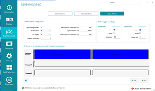
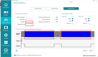
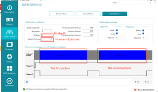
I used the splash patterns pattern and set the pattern as follows, projecting two images of splash patterns (each image is 8bit pdata[7:0] pdata[15:0])

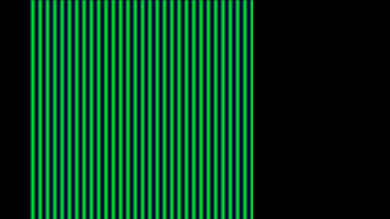
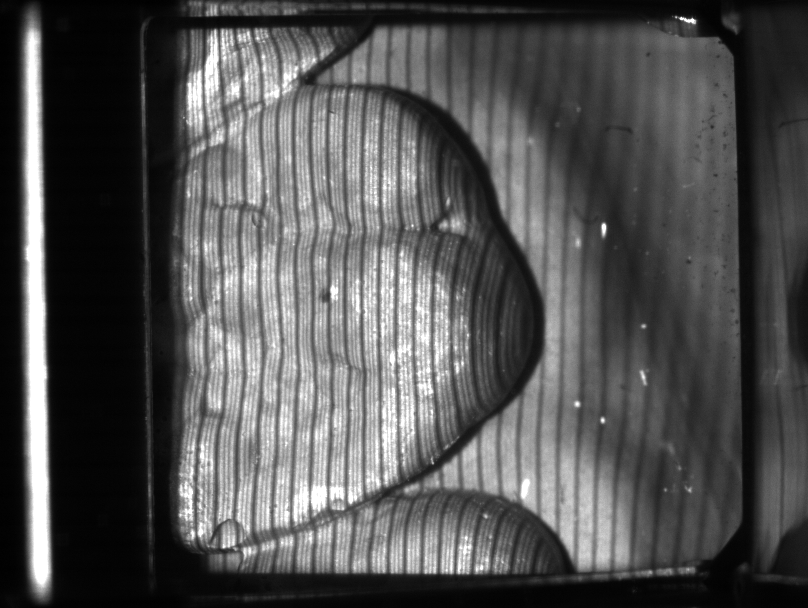
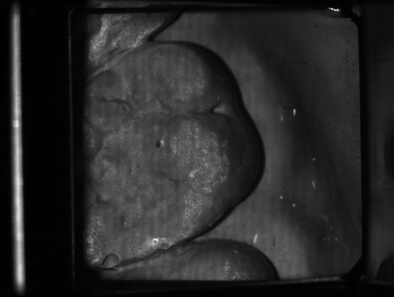
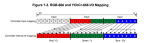
The picture I used is shown in the second picture, which is a 24-bit depth picture, and its composition can be divided into three RGB channels, the data of R channel is pdata[23:16], the data of G channel is pdata[15:8], and the data of B channel is pdata[7:0]. When I remade it, the R-channel values were all set to 0, the G-channel values were set to sinusoidal values, and the B-channel values were all set to 50. Theoretically, the two images projected should be the data of the G channel and the B channel, that is, a sinusoidal picture, and a solid color picture. Here are the images I captured with a black and white camera (the third and fourth). In fact, the third picture should be a sinusoidal change, but I looked closely and found that it was not, it was a sinusoidal period with black stripes. The fourth picture should be the data of the B channel, which should be a pure white data, but if you look at the fourth picture carefully, you will find that it is not a pure white picture, and you can vaguely see some stripes, as if it is transmitted from the third picture. The comparison shows that it seems that the two pictures affect each other, that is, the information of the third picture is transmitted to the fourth picture, and the information of the fourth picture is transmitted to the third picture. I don't know why this is. So I would like to consult you.
I wonder if it was just a problem when I made the picture. The actual projected Pdata[7:0] does not exactly correspond to the B channel of the 24BIT deep picture, and pdata[15:8] does not exactly correspond to the G channel of the 24BIT deep picture. May I ask if you have a tutorial on making 24-bit deep picture? splash patterns used in light control.

.

  • Hello Renzhen,

    Could please attach the image you are using? Also what firmware version are you using and how is your camera setup? I will try to reproduce this and get back to you.

    Best,

    Maximus

  • Hello Renzhen,

    Are you still having this issue? If you need support on this feel free to respond, for now I will mark this ticket closed.

    Best,

    Maximus

  • hello,

    I'm having problems with links like this website   DLP2010EVM-LC: DLPC347x Splash Pattern Issue and Questions - DLP products forum - DLP®︎ products - TI E2E support forums

    I want to use splash patterns mode of light control for projection, but I do not know how to set RGB565. I think it is to make a 16-bit deep image. In the following Settings, two images pdata[7:0] and pdata[8:0] can be projected. However, there is crosstalk in the two pictures I projected, and the two pictures interfere with each other. I suspect that the problem is caused when making 16bit depth pictures. I want to know which bits of pdata[7:0] correspond to RGB565, which bits of pdata[8:0] correspond to RGB565, and how to make RGB565 pictures. Why do pictures need to be saved?

  • Hello Renzhen, 

    The internal light control modes only support 1 bit monochrome, 8 bit monochrome, 1 bit RGB (1 bit/color) or 8 bit RGB (8 bits/color). Can you clarify what you mean by the two pictures interfering with each other? How are you capturing both images?

    Best,
    Maximus

  • Hello Maximus Rusl,

    splash patterns supports 8 bit depth /2 patterns per frame, so two images can be projected, namely PData[7:0] and PData[15:8], as shown below. 8-bit monochrome can project two images. Two 8-bit diagrams make a 16-bit RGB565.
    I would like to ask whether the image stored in flash is RGB565 or RGB888 when splash patterns is used.

  • Hi Renzhen, 

    The splash patterns are stored in RGB565 format. 

    Best,

    Maximus

  • Hello Maximus Rusi

             How to do RGB565 format pictures.

             RGB565 should be a 16bit deep picture, and each bit of it should correspond to PData[7:0] and PData[15:8] of light control splash patterns of DLP EVM GUI. Is there a corresponding relationship? Because RGB R occupies 5 bits,G occupies 6 bits, and B occupies 5 bits.

  • Hi Renzhen,

    You can find the relation in table 7-4 of the DLPC3478 (screenshot below). In your case Pdata[7:0] should be MSB->LSB (G4,G3,G2,B7,B6,B5,B4,B3) and Pdata[15:8] MSB->LSB (R7,R6,R5,R4,R3,G7,G6,G5). 

    Best,

    Maximus

  • hello Maximus Rusi,

    You mean that when you make a splash patterns image, you make it 24-bit deep instead of 16-bit deep. When I select patterns per frame of 2 and Bit Depth of 8, Two 8-bit depth images are projected: Pdata[7:0] should be MSB->LSB (G4,G3,G2,B7,B6,B5,B4,B3) and Pdata[15:8] MSB->LSB (R7,R6,R5,R4,R3,G7,G6,G5).
    I'll try it first, as you said.

  • Hello Renzhen,

    The controller saves the splash image as an RGB565 image by mapping the bits of a 24 bit RGB image as seen in the graph above. Yes to guarantee you get the image you are expecting, we recommend creating a 24bit image with the controllers mapping in mind. Your understanding of the 2 patterns/frame with 8 bits each is correct.

    Best,
    Maximus