DLPC7540EVM: USB connection

Part Number: DLPC7540EVM
Other Parts Discussed in Thread: DLP471TEEVM, DLP650TEEVM, , DLPC7540, PCA9539, DLPA100, TXS0102

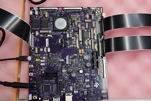
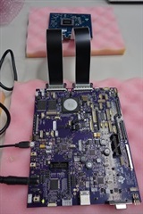
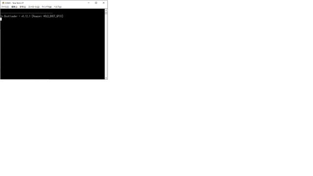
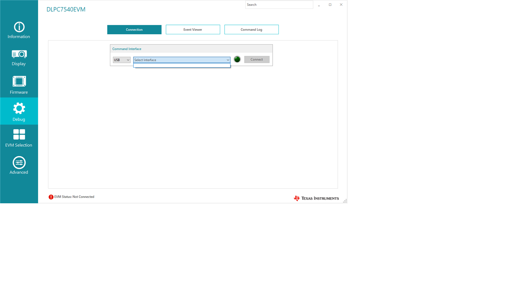
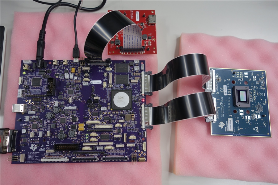
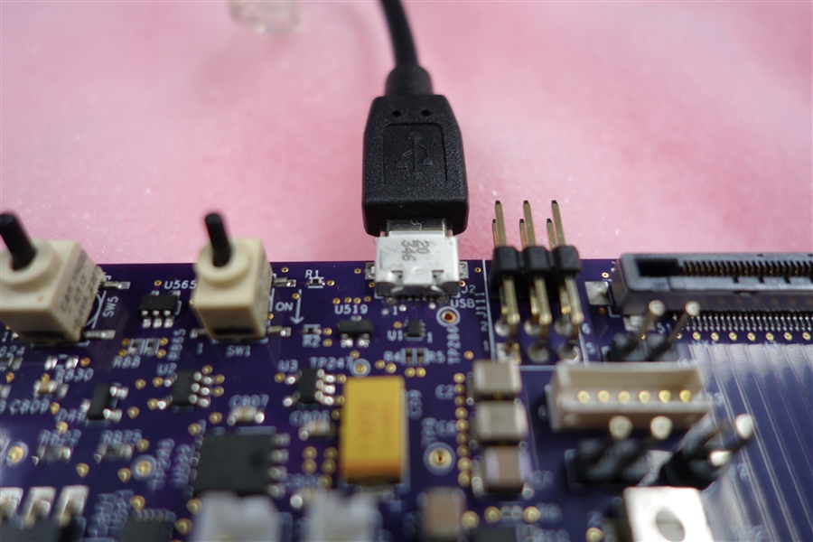
We have connected between boards and PCs by using USB according to the user's guide.

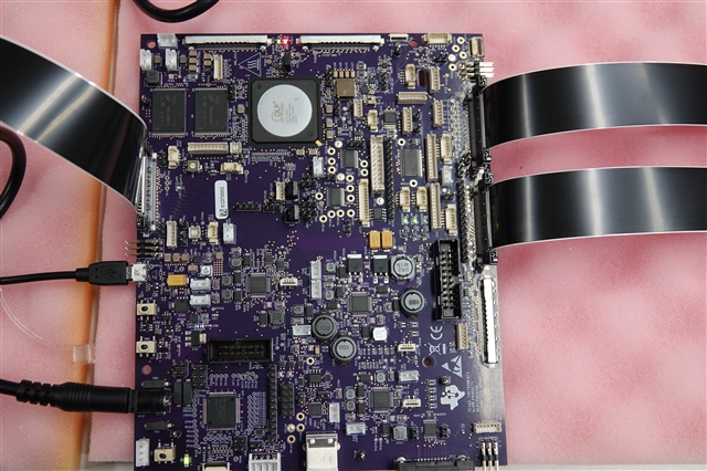
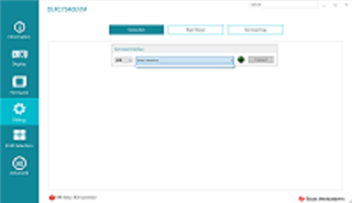
However, it is not recognized by GUI software. we are also worried that the diode D6 is red.

  • Hello,

    Thank you for providing photos of your setup. Please advise what is being plugged into the board, you have J44 and J42 connected.

    If you are trying to power a DMD EVM - DLP471TEEVM or DLP650TEEVM - this requires you to utilize J10 and J7.

    Please see Figure 2-1 of the EVM User's guide for this example.

    Best,

    Aaron

  • I am connecting a DLP650TEEVM, but the connector I am connecting is incorrect. I have connected J10 and J7 correctly according to Figure 2-1 in the EVM User Guide, but the situation remains the same.

    Is it correct that the D6 LED lights red when the power is turned on?

  • Hello,

    We are looking at the connections and checking to see what might have happened to the DMD due to the incorrect insertion of the DMD.

    To confirm, you have flipped both SW5 and SW1 in that order, correct?

    Best,

    Aaron

  • Please check the effects of incorrectly inserting the DMD power connector.

    According to the user guide, I made sure that SW5 and SW1 were off before connecting the 12V power supply, and after connecting the 12V power supply, I turned on SW5 and then turned on SW1. Only LED D6 is lit red. Other than that, D5, D7, and D15 are lit green. Next, if we connect the USB in this state and select the USB interface on the GUI, we will not be able to connect as shown in the photo above.

  • Hello,

    After inspection of J44 to J10 and J42 to J7. It seems that there were pins that have exceeded the maximum voltage.

    It seems this DMD might have been fried. Please advise if you have an alternate DMD to replace the damaged one?

    Best,

    Aaron

  • Hello,

    Please send back the debug log found through J102 (RS232), this will also highlight the issue.

    Best,

    Aaron

  • 1.Currently, there is no connection between the PC and J102. Is it possible to obtain debug logs by connecting J102 with an RS232 cable?

    2. Is the debug log displayed in "debug" - "Command Log" in the DLP EVM GUI 3.2.0.6 program? Could you tell me how to obtain the debug log?

    3. Is it an abnormal condition that only D6 is currently lit in red when the power is turned on?

  • Hello,

    1. You will need an RS232-to-USB cable to connect to your PC. This is how we read back debug logs on many of our EVMs.

    2. The debug log is sent through serial port using a baud of 115200. I would recommend using the TeraTerm application but many are available.

    3.  If only D6 is lit when the EVM is powered on; yes, this is abnormal. Per the User's Guide, D5, D6, D7 and D15 LEDs should be on when you have powered the DLPC7540EVM and flipped on SW5 and then SW1.

    Please send that debug log, this will highlight what exactly is wrong with this EVM.

    Best,

    Aaron

  • Thank you for answering.

    I immediately connected the PC and J102 (RS232) and took logs with Tera Term.

    This log was output the moment SW5 was turned on and then SW1 was turned on. Is there anything we can learn from this log?

    Contents of log

    In Boot loader = v0.12.1 [Reasonː HOLD_BOOT_GPIO]

  • For information,

    The DLP650TEEVM and DLPC7540EVM are currently available for order.

    It will be available in two weeks.

    Thank you. 

    Best regards,

    Sasaoka

  • Hello Sasaoka,

    From the debug log it seems the board is still in boot hold mode, this should mean that a jumper is connected across J9. This jumper should not be populated by default but could you check J9 that there is no jumper?

    It is still highly likely that the DMD is not communicating with the controller because of the misplacement of the connectors.

    Please attach the first couple images you attached to this discussion as they are quite small and I couldn't see details.

    If you have not yet, I recommend you read and follow the steps under section 2 (Quick Start) of the User's Guide - 'DLP Display DLPC7540 4K UHD EVM' [DLPU109].

    Best,

    Aaron  

  • Hello Aaron ,

    There is a jumper on J9.

    This is because I removed the jumper on J67 and attached it to J9 by following the instructions in Section 2.3 of Section 2 (Quick Start) of the User Guide - DLP Display DLPC7540 4K UHD EVM.

    Isn't it necessary to move the jumper from J67 to J9 in order to make the DLPC7540EVM recognize the DLP650TEEVM and operate the DMD as described in section 2.4? By the way, I have attached the log when there is a jumper on J67.

    Also, even if there is a jumper on J67, the situation where USB connection is not possible is the same.

    Contents of log
    ----------------------------------------
    Debug opened on URT0
    I2C Port 1 initialized as Master port
    I2C Port 2 initialized as Master port
    I2C Port 0 initialized as Slave port
    eeprom: Content validated
    Cal data block CWLamp not in EEPROM : Using data from flash
    Cal data block SSI not in EEPROM : Using data from flash
    Cal data block ADC not in EEPROM : Using data from flash
    Cal data block WpcSensor present in EEPROM. Data version = 4
    Cal data block WpcBrightness present in EEPROM. Data version = 4
    Cal data block XPR present in EEPROM. Data version = 4
    Cal data block XPRWaveform not in EEPROM : Using data from flash
    Cal data block SurfaceCorrection not in EEPROM : Using data from flash
    Cal data block BlendMap not in EEPROM : Using data from flash
    API version: 04.00.00
    App version: 04.00.00
    sysmon: URT Cmd Handlerfailed to start
    pca9539: Error - iox failure. APIcc = -7
    IT6807 - Configuring IT680x...
    digcontrol: Cfg complete
    IT6807 - Failed in IT680x_Write: IT680x_I2C_DRIVER_ERROR
    IT6807 - Failed in IT680x_Write: IT680x_I2C_DRIVER_ERROR
    IT6807 - Failed in IT680x_Write: IT680x_I2C_DRIVER_ERROR
    IT6807 - Failed in IT680x_Write: IT680x_I2C_DRIVER_ERROR
    digcontrol: Decoder 5 powerStandby complete
    datapath: DISP_SetDisplay failed (ret=-100)
    datapath: Set the default system mode complete
    datapath: PowerStandby Complete..
    sysmon: DLPA100 not present

    illumination: Starting SSI Initialization...
    Configured SSI Driver Type = 0.
    Configuring sensor failed : -6.
    Initializing WPC configuration...
    SSI initialization failed.
    鞳鞳鞳鞳鞳鞳鞳鞳X0J鞳鞳鞳鞳鞳鞳鞳鞳X0J鞳鞳鞳鞳鞳鞳鞳鞳X0JSysmon: Transition to normal operating mode
    Initializing WPC Failed: -6
    Initializing WPC calibration data Passed...
    Initializing WPC Brightness Table Failed: 0
    dispfmt: DISP_ConfigKeystoneByAngles failed (ret=-21)
    9
    datapath: autolock initialization passed
    digcontrol: powerNormal complete
    datapath: dig, adc, dec powerNormal
    source: SetUserSFGColor = 1
    source: SPLASH_LoadImage addresses: 0x10545f80, 0x0
    source: DisplaySplash size = 3840 x 2160
    Blank screen is set to splash
    dispfmt_CalculateDisplayArea: X, Y, Width, Height = 0, 0, 3840, 2160
    dispfmt: minPan, pan, maxPan:0, 0, 0
    data = { 3840, 0, 3840 }
    dispfmt: minScan, scan, maxScan:0, 0, 0
    data = { 2160, 0, 2160 }
    dispfmt_CalculateCroppedArea: X, Y, Width, Height = 0, 0, 3840, 2160
    dispfmt:apply_disp: activeSource = 2, dispSrc = 2

    datapath: Transition to IDLING on Vx1(ITE)

    [Actuator Type]: 0 [AWC WG Auto-Offset]: 0

    Actuator Type: 0 Unipolar: 0
    XPR Param in EEPROM: MAtch Signature
    XPR 4 Way Orientation number: 6
    XPR: Act subframe order: 2 1 3 0
    signature matched getting data from EEPROM
    ERROR: Product Configuration Invalid, System Locked
    ERROR: Product Configuration Failed Cause: Invalid Project used; please check the DMD Timing file
    illumination: DMD is invalid for this system config error in DMD_Power()
    illumination: Can't set up DMD
    sysmon: Fault in illumination transition to operating mode
    sysmon: Sysmon can't transition to operating mode
    illumination: Disabling SSI Illuminators.
    illumination.c : line - 915 : illum_enableIllumination()
    SSI_DRV_Enable() failed
    illumination: API WARNING - SEQ_POWER_DOWN_REFRESH_NOT_USED on Fusion DMD
    sysmon: _sysStandby - Transition to powerStandby
    sysmon.c : line - 723 : _sysReset()
    _sysNormalRun() failed
    sysmon: Init Complete

    ************************************

    Thank you. 

    Best regards,

    Sasaoka

  • I have attached the first two photos I sent you as requested.

  • Hello Sasaoka,

    Isn't it necessary to move the jumper from J67 to J9 in order to make the DLPC7540EVM recognize the DLP650TEEVM and operate the DMD as described in section 2.4?

    It is necessary to move the J67 to J9 when you are programming the device (step 2.4) but after it is programmed it must be placed back on J67 for normal operation - debug log is only helpful when running in normal operation. I did not remember the board was stopping at step 3 of section 2.4 and I was not detailed enough to mention that previously.

    From the debug, it seems that the IT6807 - Front-end card - is not being recognized. In normal operation, the controller needs to communicate with this card to initialize. From your last picture it seems like you don't have this connected.

    Could you please probe pin 1 of the micro-USB connector (J2)? This might be indicative of lost of communication through USB based on voltage level.

    Best,

    Aaron

  • Hello, Aaron ,

    I tried connecting the Front - end card. I also tried attaching a jumper to J67 and taking logs. 

    I have attached a photo of the state when connected and its log.

    Contents of log

    ----------------------------------------
    Debug opened on URT0
    I2C Port 1 initialized as Master port
    I2C Port 2 initialized as Master port
    I2C Port 0 initialized as Slave port
    eeprom: Content validated
    Cal data block CWLamp not in EEPROM : Using data from flash
    Cal data block SSI not in EEPROM : Using data from flash
    Cal data block ADC not in EEPROM : Using data from flash
    Cal data block WpcSensor present in EEPROM. Data version = 4
    Cal data block WpcBrightness present in EEPROM. Data version = 4
    Cal data block XPR present in EEPROM. Data version = 4
    Cal data block XPRWaveform not in EEPROM : Using data from flash
    Cal data block SurfaceCorrection not in EEPROM : Using data from flash
    Cal data block BlendMap not in EEPROM : Using data from flash
    API version: 04.00.00
    App version: 04.00.00
    sysmon: URT Cmd Handlerfailed to start
    pca9539: Error - iox failure. APIcc = -7
    IT6807 - Configuring IT680x...
    digcontrol: Cfg complete
    digcontrol: Decoder 2 powerStandby complete
    digcontrol: Decoder 5 powerStandby complete
    datapath: DISP_SetDisplay failed (ret=-100)
    datapath: Set the default system mode complete
    datapath: PowerStandby Complete..
    sysmon: DLPA100 not present

    illumination: Starting SSI Initialization...
    Configured SSI Driver Type = 0.
    Configuring sensor failed : -6.
    Initializing WPC configuration...
    SSI initialization failed.
    鞳鞳鞳鞳鞳鞳鞳鞳X0J鞳鞳鞳鞳鞳鞳鞳鞳X0J鞳鞳鞳鞳鞳鞳鞳鞳X0JSysmon: Transition to normal operating mode
    Initializing WPC Failed: -6
    Initializing WPC calibration data Passed...
    Initializing WPC Brightness Table Failed: 0
    dispfmt: DISP_ConfigKeystoneByAngles failed (ret=-21)
    9
    datapath: autolock initialization passed
    digcontrol.c : line - 194 : digcontrol_powerNormal()
    iox_edid_init() failed
    digcontrol: powerNormal failed
    digcontrol: powerNormal complete
    datapath: dig, adc, dec powerNormal
    source: SetUserSFGColor = 1
    source: SPLASH_LoadImage addresses: 0x10545f80, 0x0
    source: DisplaySplash size = 3840 x 2160
    Blank screen is set to splash
    dispfmt_CalculateDisplayArea: X, Y, Width, Height = 0, 0, 3840, 2160
    dispfmt: minPan, pan, maxPan:0, 0, 0
    data = { 3840, 0, 3840 }
    dispfmt: minScan, scan, maxScan:0, 0, 0
    data = { 2160, 0, 2160 }
    dispfmt_CalculateCroppedArea: X, Y, Width, Height = 0, 0, 3840, 2160
    dispfmt:apply_disp: activeSource = 2, dispSrc = 2

    datapath: Transition to IDLING on Vx1(ITE)

    [Actuator Type]: 0 [AWC WG Auto-Offset]: 0

    Actuator Type: 0 Unipolar: 0
    XPR Param in EEPROM: MAtch Signature
    XPR 4 Way Orientation number: 6
    XPR: Act subframe order: 2 1 3 0
    signature matched getting data from EEPROM
    ERROR: Product Configuration Invalid, System Locked
    ERROR: Product Configuration Failed Cause: Invalid Project used; please check the DMD Timing file
    illumination: DMD is invalid for this system config error in DMD_Power()
    illumination: Can't set up DMD
    sysmon: Fault in illumination transition to operating mode
    sysmon: Sysmon can't transition to operating mode
    illumination: Disabling SSI Illuminators.
    illumination.c : line - 915 : illum_enableIllumination()
    SSI_DRV_Enable() failed
    illumination: API WARNING - SEQ_POWER_DOWN_REFRESH_NOT_USED on Fusion DMD
    sysmon: _sysStandby - Transition to powerStandby
    sysmon.c : line - 723 : _sysReset()
    _sysNormalRun() failed
    sysmon: Init Complete

    ******************************************************************************************************************

  • I inserted the micro USB cable into J2 and checked the voltage at pin 1.

    It was +5.027V (between 1pin and 5pin).

    I don't think there is anything wrong with it.

    Just to confirm, is there only one jumper to be inserted on the DLPC7540EVM board, J67 or J9?

    Is there another place to insert a jumper?

    Thank you. 

    Best regards,

    Sasaoka

  • Hello Sasaoka,

    It seems that the DMD is not being recognized. This means the DMD has been damaged with the incorrect use of the jumpers and we should not debug this further as we understand the DMD has been damaged.

    We are sorry we could not provide and easy solution for this, but please continue with replacing at least the DMD EVM. It would be advantageous to replace the controller board as well.

    Please reach out to us if there are additional issues after receiving the new hardware through another thread. 

    Before these boards are received, I would again advise to read through the User's Guide to have confidence when utilizing the replacement. At a minimum, please follow along with the guide when you receive the hardware.

    Best,

    Aaron

  • Hello Aaron,

    I understand that Mr. Aaron looked at the log I sent and determined that the DMD was malfunctioning, is that correct?
    Also, I understand that the cause of the DMD failure was that the wrong connector was inserted at the beginning and the power was turned on, but is that correct?
    It is difficult to understand that the fact that the USB of the DLPC7540 EVM is not recognized on the GUI is related to a failure of the DMD.

    What do you think about?


    Anyway, as soon as I get the new set (DLPC7540EVM and DLP650TEEVM), I will test it immediately according to the user guide.
    By the way, I have a question.


    <Question>
    1. In the quick start in 2 of the user guide, there is no mention of connecting the Front-end board to the DLPC7540EVM when programming to the EVM.

     Is this connection necessary?

    2. The timing for connecting the front end board is as follows: After completing steps 1 to 4 in Section 2.4, turn off the power,

     connect the front end board to EVM, and then turn on the power (SW5 ON → SW1 ON). Is this correct?

    That’s all.

    Thanks

    Best regards,

    Sasaoka

  • Hello Sasaoka,

    After comparing the connection from controller side (J42) and DMD side (J7), it's shown that not just the HSSI pins were exposed to 5V. The entire ground plane of the DMD was exposed to 5V and in some cases might have caused other damage back on the controller board through not just the DLPC7540 but peripheral ICs, such as the TXS0102 level shifter which has an absolute maximum supply voltage of 4.6V (on the A side of the chip).

    The point is, is that there are many things that could have been damaged from the DMD board back to the controller board and we don't intentionally break out boards in the lab to see all of the possible outcomes to assist with debug.

    1. It is not necessary to have the front-end board connected while programming the DLPC7540 EVM in boot loader mode but during regular function it is necessary for basic reprogramming.

    2. If the guide is followed in chronological order, within step 2.4 the front-end and DMD boards are connected but the jumper is placed on J9 (Boot hold) instead of J67 (5V to Front-end).

    Additionally, when programming the board in boot hold mode it is not required to have either of these boards connected. When utilizing the GUI and programming an image file, it is necessary to have both of these boards connected.

    Best,

    Aaron

  • Hi Aaron,

    Thank you for all your answers.

    As soon as I get a new board, I will try programming it according to the user guide. We will contact you again if any problems arise.

    Thank you for your strong support so far.

    Best regards,

    Sasaoka

  • Hello Sasaoka,

    I am going to mark this thread as resolved.

    If another problem presents itself after your new hardware is received, please feel free to open another thread and me or my team will be happy to help any way we can!

    Best,

    Aaron