This thread has been locked.

If you have a related question, please click the "Ask a related question" button in the top right corner. The newly created question will be automatically linked to this question.

DLP2000: Connection with DLPC2607

Part Number: DLP2000
Other Parts Discussed in Thread: TIDA-01473, DLPDLCR2000EVM, DLPC2607, , DLPA1000

Hello,

I'm making a feasibility study on a small projector design.

I've purchased the evaluation board DLPDLCR2000EVM and checking its design, together with the reference design numbered TIDA-01473.

Now my question is:

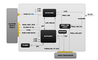
 - where can I find a reference or an example schematic regarding connection between DLPC2607 and DLP1000?

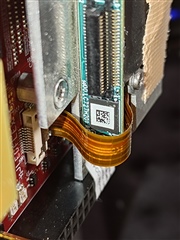
  The schematic included in TIDA-01473 only refers to the connector for DMD, not the wiring inside the flex cable which is attached to DLP2000.

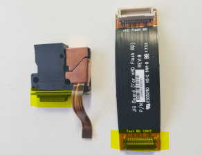
 It is not just easy to imagine them from the signal names and, what's more, I visually find a Flash memory W25X40CL just on the back side of DLP2000,

which is not described nor mentioned in DLPC2607 documents.

Thank you in advance!

  • 2607 has the following signals and 2000 not:

    DMD_SAC_CLK

    2000 has and 2607 not:

    scan_test

  • Hello User,

    Welcome to the E2E forum. Thank you for your business!

    The Power Management IC for the DLPDLCR2000EVM is the PAD1000, which also referred to as the DLPA1000. The schematic TIDA-01473 describes the PMIC connections on page 2.

    The wiring inside the flex cable is labeled as pins 1 through 52 in 'CONNECTOR FOR DMD FLEX CABLE' which correspond to the order of the wires in the cable.

    The flash IC W25X40CL found on your EVM is functionally the same as W25Q16DW on the schematic. The W25Q16DW has been discontinued so an alternative was found. The schematic will be updated.

    Best,

    Maxine

  • Dear Maxine,

    thank you for your prompt response.

    Unfortunately the flash you mentioned is "U3" on the EVM board, but what I saw was on the back side of DLP2000, close to the other end of the flat cable.

    How are the signals of flat cables connected with DLP2000?

    I would like to know the connection

    between the flat cable and DLP2000;

    NOT between the flat cable and DLPC2607/DLPA1000.

    If the information above is the optical engine supplyer scope, could you kindly explain the connection among DLP2000 and DLPC2607/DLPA1000?

    The information about the EVM is very helpful but only discloses DLPC2607/DLPA1000 side. The other side, connection of DLP2000, is not found yet.

  • Hello,

    The signals between the DLPA1000 and DMD are Vbias, Vreset, and Voffset. The PMIC also controls Vled for the optical engine LEDs. Vbias, Vrst, and Vofs are pins 32, 40, and 29 on the flex cable, respectively. 

    The other signals on the flex cable, such as the DMD data, originate from the DLPC2607 controller.

    We do not develop the optical engine of the EVM. The optical engine mounts directly to the provided large flex cable and should not be altered.

    Best,

    Maxine

  • Hello, 

    Yes I found the information you mentioned on the datasheets, but some points are still unclear.

    As you can see on the following table, not all the signals are just comparable.

    <<DLPC2607>> <<DLP2000>>
    DMD_D0 DATA(0)
    DMD_D1 DATA(1)
    DMD_D2 DATA(2)
    DMD_D3 DATA(3)
    DMD_D4 DATA(4)
    DMD_D5 DATA(5)
    DMD_D6 DATA(6)
    DMD_D7 DATA(7)
    DMD_D8 DATA(8)
    DMD_D9 DATA(9)
    DMD_D10 DATA(10)
    DMD_D11 DATA(11)
    DMD_D12
    DMD_D13
    DMD_D14
    DMD_DCLK DCLK
    DMD_LOADB
    DMD_SCTRL SCTRL
    DMD_TRC
    DMD_DAD_BUS DRC_BUS
    DMD_DAD_STRB DRC_STROBE
    DMD_DAD_OEZ DRC_OEZ
    DMD_SAC_BUS SAC_BUS
    DMD_SAC_CLK
    SCAN_TEST

    Can the following signals remain "not connected"?

    <DLPC2607>

    DMD_D12, DMD_D13, DMD_D14, DMD_LOADB, DMD_TRC, DMD_SAC_CLK

    <DLPA1000>

    SCAN_TEST

    I simply doubt this connection, since "DMD_SAC_CLK" seems to be the clock source for DMD_SAC_BUS but there's no connection for this.

    It's not simply understandable why DLP2000 can work without this clock signal.

    I also attach a photo regarding the flash beside the DLP2000. You can see an IC, on which a QR code is attached.

    Is it really right, that this IC is "not necessary" at all and I can omit it for my product?

  • Hello,

    The DLPC2607 controller has more extensive functionality than this EVM requires. Signals that are output from the controller but are not  used in the EVM design are:

    - DMD_D12, DMD_D13, DMD_D14

    - DMD_TRC

    - DMD_SAC_CLK - The DMD_SAC_BUS is clocked in by DCLK rather than SAC_CLK

    - SCAN_TEST

    However, DMD_LOADB is essential to the design. The corresponding signal has the same name, LOADB.

    In addition, the IC you refer to in the picture is a flash IC. This design is by our optical engine manufacturer so unfortunately we cannot give you any feedback regarding your specific design. I hope I was able to answer your questions. Let me know if there is anything else I can do to help.

    Best,

    Maxine 

  • Thank you very, very much. Excellent, this is the EXACT information I really needed. 

  • I'm very glad I could help. If you have any further questions, don't hesitate to start a new thread.