This thread has been locked.

If you have a related question, please click the "Ask a related question" button in the top right corner. The newly created question will be automatically linked to this question.

DLP471TEEVM: Failure once again

Part Number: DLP471TEEVM
Other Parts Discussed in Thread: DLPC7540EVM, DLPC7540, DLP471TE

Dear TI DLP Experts,

I am using a replaced (since the original also gave up on us) EVM kit DLP471TEEVM with DLPC7540EVM.
The sudden failure to start has been observed once again without any damages and lack of incidents.
However, the problem seems to be different this time around. 
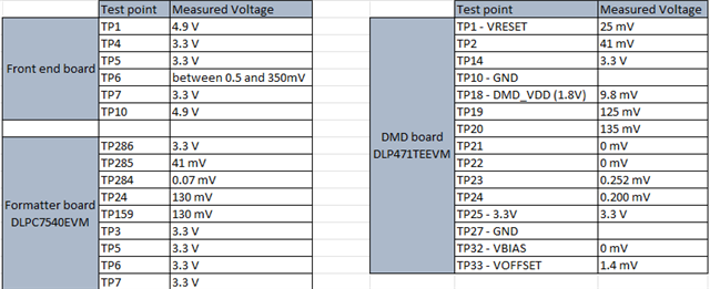
I have followed all troubleshooting steps as described in the previous case (https://e2e.ti.com/support/dlp-products-group/dlp/f/dlp-products-forum/1217119/dlp471teevm-dmd-error-dmd-not-working
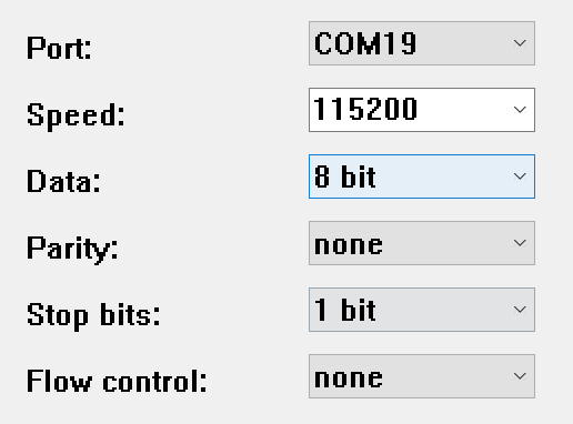
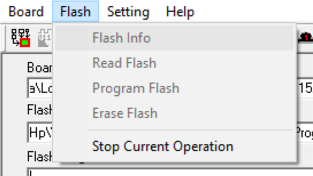
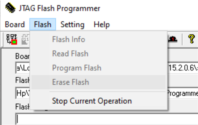
Unfortunately, this pair does not get recognized by the PC and the serial bus connection is also not populated by any information.
The lights on the controller board that are on: D5, D7, D15, D52 - constant green color; D6 - constant red color. Furthermore, all the boards (DMD, Controller, HDMI) seem fine and have no signs of burned electronic components. I have also checked all cables for connectivity and they seem fine.
We are looking for either some help or replacement (however we might go with a different model).
Thanks in advance!

Kind regards,
Dimitar

  • Hello Dimitar,

    I am getting a member from my team to help you look at this.

    Could you please help us understand what has been done in the past to cause this sudden failure? I understand you listed out the steps in the past, but is it those same steps?

    Also, it seems that your serial bus connection is also not available? Could you expand on this? Is nothing being seen or bad information is being sent?

    Best,

    Aaron

  • Hello Aaron,

    thank you for your time.
    The usage of the DMD is the following: we illuminate it under 34 degrees angle with a broadband wavelength with intensity not exceeding the values specified in the data sheet. We use a mirror to reflect the light onto it. Then we have optics (which do not physically connect to the DMD housing) to show the projection. 
    The EVM boards are enclosed carefully in a 3D printed housing and held in place at the fixture points as per design requirements. No electrical components come in touch with the housing and the flex cables are tightly installed without being constantly plugged and unplugged (with the exception of the power cable, USB cable and HDMI cable). We use the DMD very sparingly in that we have illumination of it only for a minute or maximum 3mins at a time and conduct experiments maybe every other week. We also use a small fan (externally powered) fixed to the housing for cooling (even though we do not really need any cooling since the temperatures do not exceed those in the specification). The small fan also does not physically come into contact with the boards or EVM elements. We use the DMD to project image sequences via the HDMI. The power cable is according to specification and the USB/HDMI cables are pretty standard. We just plug in power, USB, HDMI and then power on (SW5 then SW1) the EVM board. After that the DMD initializes and almost immediately starts displaying from the HDMI source. Some days ago I turned it on and there was no image displayed. I opened the EVM GUI and the USB did not show up. There has not been any difference in usage and just the day before the DMD was working fine (we have not even touched the setup). I have also tested different systems (laptops) and changing USB/HDMI cables, but still nothing. I tried restarting - nothing. I inspected the boards and there is no visually anything burned or damaged at all. It looks like new basically. I have also tested the flex cables for connectivity - work fine. Next, I tested the serial bus port (as per the instructions of the last post mentioned) but this time it just does not populate and there is no information being sent. I tried also booting up the system with the jumper cable in J9 position (programming mode) but still nothing.
    Let me know if there are any other questions.
    Thanks!

    Best,
    Dimitar

  • Hello Dimitar,

    Again, my team member will respond to this.

    For clarity, you didn't have anything return from the debug log using Teraterm and J102 Serial port with or without J9 populated?

    Best,

    Aaron

  • Hi Aaron,

    yes, that is correct. There was nothing returning from the debug log using Teraterm and J102 Serial with or without J9.

    Thanks,
    Dimitar

  • Hello Dimitar,

    My team member is currently on holiday and will return shortly. I am sorry for the delay in response.

    We would like to help as much as we could and it seems the best way to move forward would be to start by testing power supply voltages and make sure everything is being supplied as intended.

    Could you help us understand the status of the board through telling us which LEDs are on when both switches are switched on? Also the recorded voltages of the DLPC7540 power banks - seen on page 10 of the schematic?

    Best,

    Aaron

  • Hi Aaron,

    Here is what I measured from the boards.
    Unfortunately, I am unable to find the schematic you are referring to. Page 10 in the User Manual has no schematic. I do not know which test points are the "power banks". TP6 is varying voltage like TP24,159,19 and 20, and the value should be something like 130 mV.

    The LEDs I have mentioned before, but here they are again: D5, D7, D15, D52 - constant green color; D6 - constant red color.
    Thanks. I am looking forward to solving this or getting a replacement ASAP, because our projects are still on hold...

    Best,

    Dimitar

  • Hello Dimitar,

    Thank you for the information! The schematics can be found under the "Design Files" section of the DLPC7540EVM page.

    I'll have my more effective team members look at this shortly. Thank you again for sending us this valuable information!

    Best,

    Aaron

  • Hi Aaron,

    okay, thanks!
    I found the schematics. The pins on the board are not named clearly and I would not know which pin I am measuring.
    Am I searching for some small resistor that is burned and to replace it myself? I do not have the tools for that... 

    I would like to get the product reimbursed and I can send it back for more detailed testing.

    Best,

    Dimitar

  • Hello Dimitar,

    The link provided previously can still be used to reach our customer service department.

    Unfortunately, this board is not simple due to the high functionality that is offered. Fortunately, it has been evaluated and marked when it it was built, and was shown to meet our standards.

    Because you have already had this happen before, it is indicative that something is being used abnormally. I'd like to deduce where the issue is at; where it could be (1) on the controller board or (2) on the DMD board. They are connected in normal functionality by flex cables.

    Firstly, please test the connection of the controller board by first powering down the whole system, disconnecting the flex connections to the DMD board, and powering back on the system. You will need to read back the debug log and the GUI information.

    Secondly, please test the connection of the controller board following the same steps, but moving the jumper connection from J67 to J9 - again reading back the debug log and GUI information.

    Best,

    Aaron

  • Hi Aaron,

    please excuse my frustration. 
    The supplier has told us that to get the part reimbursed we need to troubleshoot it with TI first. I called your product service for expedited troubleshooting and they referred me the online-chat where I was then referred to this forum, since nobody could help troubleshoot.
    To clarify - this is not the same problem as before, because previously there was serial data coming through and GUI errors were indicated.
    Now it just does not respond at all, besides the test points and LEDs as already mentioned.

    I tested as per your instructions:
    Test 1 - DMD board disconnected, Front-End board connected. J67 installed. Results: DLP GUI does not show the USB as available port and no connection can be established. J102 Serial Port does not populate any information.
    Test 2 - DMD board disconnected, Front-End board connected. J9 installed. Results: DLP GUI does not show the USB as available port and no connection can be established. J102 Serial Port does not populate any information.
    Test 3 - DMD board and Front-End board disconnected. J67 installed. Results: LP GUI does not show the USB as available port and no connection can be established. J102 Serial Port does not populate any information.
    Test 4 - DMD board and Front-End board disconnected. J9 installed. Results: LP GUI does not show the USB as available port and no connection can be established. J102 Serial Port does not populate any information.

    For the TeraTerm serial configurations I tried both 9600 and 115200 speeds, but got no luck there either.

    Let me know what's next!

    Thanks and best,
    Dimitar

  • Hello Dimitar,

    I appreciate your patience and am sorry to hear you are experiencing issues with this. I'm getting my team members to respond to you here shortly. They are much more familiar with this board than I am and will be able to assist at a deeper level.

    The serial configuration that we utilize is 115200 speeds.

    Please provide the version of the software you are working with and again they've respond to you shortly.

    Best,

    Aaron

  • Hi Aaron,

    Okay, thanks!

    The TeraTerm is version 5.2 and the DLP EVM GUI is 3.2.0.6.

    I am looking forward to the next steps.

    Best, 
    Dimitar

  • Hi Dimitar,

    This is Siddharth and I will continue this query further.

    First we need to ensure that the power supply to the DLPC7540 EVM is proper, so can you please share the details of the power supply you are using (current rating and voltage level) to power the system. Improper power supply can cause instability in the system.

    Also before connecting the power, disconnect the DMD board and place the J9 jumper to ensure that the system goes to bootloader state. Now connect the power. Verify that you have connected the USB and J102 serial port. After powering please check the device manager if both the connection are showing up. The settings for serial communication are shown in the below image. Ideally if the bootloader is not corrupted, the USB connection should show up and you should be able to get the debug log. If not then we will proceed further.

     Also please share a picture of your setup (DLPC7540 EVM and the power supply connection to it)

  • Hi Siddharth,

    The power supply we use has 12V 5A DC output (exact model is SGA60E12 from Mean Well). 

    The device manager recognizes that I have plugged the USB adapter J102 but not the one from J2.
    The TeraTerm does not populate with anything.

  • Hi Dimitar,

    Sorry for the late response. The power supply looks proper to me. I suspect that your bootloader has gotten corrupted and we will need to reprogram it to bring the USB connection back. Please follow the steps mentioned in the PDF attached. Do let me know if you face any problems in following the steps mentioned in the PDF or even after completing all the steps the system does not come up.

    Again I apologize for the delay in response from my side.

    reprogram_bootloader.pdf

  • Dear Siddharth,

    thank you so much!
    I will order the parts and attempt this fix and come back to you in the following week/weeks.
    Have a good weekend.

    Best,

    Dimitar

  • Hi Siddharth,

    i have finally managed to try the reprogramming of the bootloader. The short version - it did not work.
    The long version - I ordered all the parts needed and followed your instructions. During the installation the jtag programmer did not display the same image for the chip model as in your instructions.

    However, I was able to erase and install the bootloader and it was successful.
    I found a command called verification (of the flash image) and got the following error after installation:

    I then went on to the next steps of the instructions - to check whether the DLP GUI was recognizing the board.
    It did not recognize it (same as before):

    I also checked Tera Term and got nothing back (same as before). 
    To summarize - the bootloader reprogramming was not successful. 

    Best,
    Dimitar

  • Hi Dimitar,

    Let me check on this and get back to you as soon as possible.

    Thanks,
    Siddharth

  • Hi Dimitar,

    Ideally when you do the verify flash, it should return successful but you report as failed. After doing the detect chain step (5th step) in the bootloader, can you follow the below steps. Also do not change the size in hex to be 0x80000, let it be the default value.

    1. Read flash info

    2. Click on erase, and erase atleast 15 blocks. Click exit once Erase is completed.


    3. Now click on program icon and wait until it is completed

    4. Click on verify icon and make sure it is successful

    Now continue from Step 8 of the original instructions I sent. Also the chain image being detected as DLPCX54X is okay. Also can you send a picture of the connections you have made, to make sure there is no problem due to them.

    Thanks,

    Siddharth Khandelwal

  • Hi Siddharth,

    I hope you are doing well.
    After a long period of frustration, I decided to order a new model of DMD EVM board. 
    We are able to continue our project and I have finally found some time to give this defective one another shot.
    I did as you said and got a 100% verification.

    I even go the DLP GUI connected.

    Then I tried to connect the DMD with the 2 flexible cables. 
    Unfortunately, nothing showed up on the DMD.
    To try to troubleshoot again I loaded Tera Term through the J102 Serial Port.
    I received the following output:

    I tried to re-upload the firmware via the DLP GUI with the official image Flash_DLPC7540_DLP471TE_LED.img, but am getting an error:

    Unfortunately, I do not think I can dedicate much more time to this issue.

    Could we resolve it somehow and have it sent back or reimbursed at least?
    As I have said, we have moved on to a different DMD EVM model and my limits have been reached.

    Let me know and thanks for all the help so far.

    Kind regards,
    Dimitar

  • Hi Dimitar,

    I apologize for the inconveniences caused to you. It is good that you are getting logs on the J102 serial port. I would advice you to place the Jumper J9 first before powering on the system so that the system goes in Bootloader mode when powering up. Confirm from the UART logs that the system has entered Bootloader mode. Now try flashing the official image provided through USB. Then power off the system and move the jumper from J9 to J67. Now power on the system.

    Currently since you have updated the Bootloader, and there is no APP present in the flash image, the flashing of the image might fail due to this.

    Concerning any reimbursements or replacement for products, please refer to this page https://www.ti.com/support-quality/additional-information/customer-returns.html?keyMatch=RETURN%20POLICY for additional information regarding TI's Return policy.

    Thanks,

    Siddharth