This thread has been locked.

If you have a related question, please click the "Ask a related question" button in the top right corner. The newly created question will be automatically linked to this question.

DLPC7540EVM: LED PWM RED signal output is not output

Part Number: DLPC7540EVM
Other Parts Discussed in Thread: PCA9539, DLPA100, DLPC7540, DLP650TE

Hello

We set up the purchased DLPC7540EVM and DPL650TEEVM according to the user guide.

I confirmed that I ran the Quick Start in Section 2 in order and completed up to 4.d in Section 2.4 and completed up to Figure 2-5.

Next, I connected the Front end board to the Formatter board. I also confirmed the output on the DMD screen for the test pattern on the DMD and the external input of HDMI.

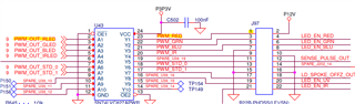
Next, I checked the LED enable signal and PWM signal on the connector on the DLPC7540EVM board, and found that the RGB enable signal was output,

but the RED PWM signal was not output. G and B PWM signals are output.

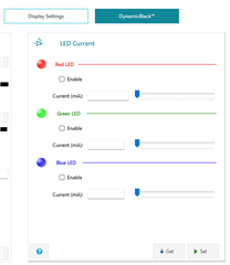
Also, if you change the Current in LED Current of "Display" - "DynamicBlack" on the GUI, the signal output of G and B will change, but only red will remain LOW.

The location being observed is pin 1 of connector J97. G and B are 3 and 5 pins.

Why?

Best regards,

Sasaoka

  • Hello Sasaoka,

    Looking at the GUI, does the checkbox below the "Red LED" and associated line happen to be checked or not?

    Can you perform a "Get" down at the bottom to see the status?

    Best,

    Aaron

  • Hello Aarron,

    The checkbox under "Red LED" and its associated line in the GUI is checked. I checked the status by running "Get" at the bottom.

  • Are there any jumpers to set on the EVM board when operating the LED? Or is there any software I need to download?

  • Hello Sasaoka,

    Thank you for checking the status of the box, looking through the schematic.

    It isn't immediately shown but you need to jump J505 across 1-2 to select GPIO_59 as Red PWM. This jumper is found next to J10 and the ASIC.

    Best,

    Aaron

  • Hello Aaron,

    At first, I shorted J505 with a jumper between 1 and 2 according to your instructions. As shown in the photo.

    However, the RED PWM signal is not output. (Check No,1 pin of connector J97)


    Is there no other setting required?


    The duty of the G and B PWM output waveforms will change when we change the GUI LED current value, but RED will not change.

    It's always ’’Low’’.

    Best regards,

    Sasaoka

  • Hello Sasaoka,

    This is suspicious and I'll have to reach out to the software side of my team to comment on this.

    As I am reaching out to them, it would be helpful to include a debug log from J102 RS232 port while the device is being powered and while the GUI settings are being manipulated.

    Thank you,

    Aaron

  • Hello Aaron,

    I got the debug logs from the J102 RS232 port when the EVM is powered on.

    Also, during GUI operations, we confirmed that no matter what operations are performed within [DynamicBlack], nothing is displayed in the log.

    Among GUI operations, it appears in the log when you press 'Switch to external Video' in [Video and Color] and when you operate in [Pattern and Images].

    Do I also need that log?

    This time, I will send the log that is displayed when the power is turned on. It is below.

    ************************************ log *******************************************************

    Debug opened on URT0
    I2C Port 1 initialized as Master port
    I2C Port 2 initialized as Master port
    I2C Port 0 initialized as Slave port
    eeprom: Content validated
    Cal data block CWLamp not in EEPROM : Using data from flash
    Cal data block SSI present in EEPROM. Data version = 0
    Cal data block ADC not in EEPROM : Using data from flash
    Cal data block WpcSensor present in EEPROM. Data version = 4
    Cal data block WpcBrightness present in EEPROM. Data version = 4
    Cal data block XPR present in EEPROM. Data version = 4
    Cal data block XPRWaveform not in EEPROM : Using data from flash
    Cal data block EdgeBlend not in EEPROM : Using data from flash
    Cal data block SurfaceCorrection won't fit in EEPROM : Using data from flash
    Cal data block SurfaceCorrection not in EEPROM : Using data from flash
    Cal data block BlendMap won't fit in EEPROM : Using data from flash
    Cal data block BlendMap not in EEPROM : Using data from flash
    API version: 4.5.0.0.0.0
    App version: 4.5.0.0.0.0
    sysmon: URT Cmd Handlerfailed to start
    pca9539: Error - iox failure. APIcc = -7
    IT6807 - Configuring IT680x...
    digcontrol: Cfg complete
    digcontrol: Decoder 2 powerStandby complete
    digcontrol: Decoder 5 powerStandby complete
    datapath: PowerStandby Complete..
    sysmon: DLPA100 not present

    illumination: Starting SSI Initialization...
    Configured SSI Driver Type = 0.
    Configuring sensor failed : -6.
    Initializing WPC configuration...
    SSI initialization failed.
    Sysmon: Transition to normal operating mode
    Initializing WPC Failed: -6
    Initializing WPC calibration data Passed...
    Initializing WPC Brightness Table Failed: 0
    datapath: autolock initialization passed
    digcontrol.c : line - 194 : digcontrol_powerNormal()
    iox_edid_init() failed
    digcontrol: powerNormal failed
    digcontrol.c : line - 194 : digcontrol_powerNormal()
    iox_edid_init() failed
    digcontrol: powerNormal failed
    digcontrol: powerNormal complete
    datapath: dig, adc, dec powerNormal
    source: SetUserSFGColor = 1
    9
    dispfmt_CalculateDisplayArea: X, Y, Width, Height = 0, 0, 3840, 2160
    dispfmt:apply_disp: activeSource = 1, dispSrc = 1
    source: SPLASH address: 0x10522d7c
    source: DisplaySplash size = 3840 x 2160
    Blank screen is set to splash
    dispfmt_CalculateDisplayArea: X, Y, Width, Height = 0, 0, 3840, 2160
    dispfmt: minPan, pan, maxPan:0, 0, 0
    data = { 3840, 0, 3840 }
    dispfmt: minScan, scan, maxScan:0, 0, 0
    data = { 2160, 0, 2160 }
    dispfmt_CalculateCroppedArea: X, Y, Width, Height = 0, 0, 3840, 2160
    dispfmt:apply_disp: activeSource = 2, dispSrc = 2

    datapath: Transition to IDLING on Vx1(ITE0)
    dispfmt_ConfigManualWarp(): LensCorrection enabled = 0
    Actuator EEPROM size - 6 (where 0 = 0.125k,1 = 0.25k,2 = 0.5k,3 = 1k,4 = 2k,5 = 4k,6 = 8k)

    [Actuator Type]: 128 [AWC WG Auto-Offset]: 0

    Actuator Type: 128 Unipolar: 0
    XPR Param in EEPROM: MAtch Signature
    XPR 4 Way Orientation number: 22
    XPR: Act subframe order: 0 3 1 2
    XPR_4WAY_TIActGetActuatorData(): Read from EEPROM failed
    XPR_4WAY_TIActGetActuatorData(): Read from actuator failed!!!
    datapathf: XPR_4WAY_Init Failed
    SUCCESS: Product Configuration Valid, System Unlocked
    Controller Info: Id = 0x01030059, Name = DLPC7540
    DMD Info: DeviceId = 0x600D0096, FuseId = 0x00070008, FuseBitString = 00010000111111111, Name = DLP650TE_ECD_p65_UHD
    illumination: Enabling SSI Driver...
    sysmon: Transition to normal mode complete
    sysmon: Completed _sysReset
    sysmon: Init Complete
    Startup Logo display time completed - 5097 milliseconds. Starting connector scan

    ------------------- SCANNING CONNECTOR : Vx1(ITE0) ----------------
    Warning: No AFE1000/HW communcation found while attempting to place stand-by (However connector table seem to have a VGA entry)
    IT6807 - iteState is ITE_POWERUP
    digcontrol: Decoder 5 powerStandby complete

    datapath: Transition to SCANNING on Vx1(ITE0)
    digcontrol: ConfigureForSearch complete
    Event: Source Change Detected on channel
    Event: DSM Locked on channel
    digcontrol: FillSourceConfig - srcConfig:
    TotalArea.PixelsPerLine - 4400,
    TotalArea.LinesPerFrame - 2250,
    ActiveArea.FirstPixel - 384,
    ActiveArea.FirstLine - 82,
    ActiveArea.PixelsPerLine - 3840,
    ActiveArea.LinesPerFrame - 2160,
    PixelClockFreqInkHz - 594000,
    inputFrameRate - 59,
    srcColorType - RGB.
    srcConfig->IsInterlaced - FALSE,
    digcontrol: FillSourceConfig complete
    Is3D = FALSE
    dispfmt: DEI Disabled, Field Scaling Disabled
    dispfmt: Input frame rate is 59Hz
    dispfmt: input resolution: 3840 x 2160
    dispfmt_CalculateDisplayArea: X, Y, Width, Height = 0, 0, 3840, 2160
    dispfmt: minPan, pan, maxPan:0, 0, 0
    data = { 3840, 0, 3840 }
    dispfmt: minScan, scan, maxScan:0, 0, 0
    data = { 2160, 0, 2160 }
    dispfmt_CalculateCroppedArea: X, Y, Width, Height = 0, 0, 3840, 2160
    dispfmt:apply_disp: activeSource = 0, dispSrc = 0
    ******* Try to set Color Profile 0 *******
    pictcont: Active Display is 0
    pictcont: Set White Peaking: 0
    pictcont: Set gamma 0
    pictcont: Sharpness 16
    pictcont: cscIndex 0
    pictcont: tableIndex 0

    datapath: Transition to MONITORING on Vx1(ITE0)
    gui: ccode 5 receiving GUI message

    ******************************************************************************************

    I have a request.

    Is it possible for your company to prepare the same board environment and check that LED RED PWM is not output?

    I think it is very important to check whether the same phenomenon occurs in the same environment.

    Yours sincerely, 

    Sasaoka

  • Hello Sasaoka,

    Could you put a probe to pin 2 of J505? This connects to GPIO 59 and this should be putting out a PWM signal equal to that of GPIO 60  and GPIO 61 of the DLPC7540.

    In my lab evaluation, the enable line was always high (pin 1 of J97) this went low when the red was disabled via the GUI.

    Please advise if this is different from your board.

    I'll get a member of my team familiar with the software to respond to the GUI errors - this might stem from the same issue.

    Best,

    Aaron

  • Hello Aaron,

    I attached a probe to pin 2 of J505.

    Then, when the power was turned on, the RED PWM signal was output.

    Furthermore, we confirmed that when changing the RED Current on the GUI, the PWM duty of the probed signal changed correctly.

    Good job Aaron!!

    Is it possible to output RED PWM from pin 1 of connector J97?

    Best,

    Sasaoka

  • Hello Sasaoka,

    I'm glad this resolved your issue!

    I'm not sure what's needed here. The Red PWM connection is shown below. The J97 connector is meant to connected to an LED illumination system - this isn't included with the EVM kit. 

    If there is not proper functionality as shown in the schematic, please advise. Otherwise, please accept this as your resolution as I close this thread.

    If additional questions about the system are necessary, please open another thread afterward.

    Thank you,

    Aaron

  • Hi Aaron,

    The problem is not resolved yet.
    The problem can be solved by outputting RED PWM from pin 1 of connector J97 as shown in the circuit diagram.

    Until this fix is made, your board will still have a bug.

    Please fix this bug.

    We manufacture lighting systems based on circuit diagrams.

    The lighting system only works when RGB PWM is output from this J97. Support is required until we can fix the EVM firmware, install the corrected version on our board, and get it fully operational.

    What I don't know is how to install that modified firmware on our EVM. Please tell me that.

    Yours sincerely, 

    Sasaoka

  • As for information,

    In Japan there is a holiday called Golden Week, and tomorrow, April 27th to 29th and May 3rd to 6th, are holidays.

    Please forgive me for not being able to respond at that time.

    Best,

    Sasaoka

  • Sasaoka,

    If the red LED output from DLPC7540 controller is not seen at J97.1 please trace back through U43.23 and U43.1 testing if U43 is still operating. If it isn't U42 will need to be replaced if this board is out of warranty.

    If it is not seen at U43.1 please check J505.2 and then J505.1 ensuring the jumper is operating from pin 2 as you've said you can see the output previously.

    I attached a probe to pin 2 of J505.

    Then, when the power was turned on, the RED PWM signal was output.

    Best,

    Aaron

  • Hey Sasaoka,

    I'm glad this jumper was the solution!

    Best,

    Aaron