Other Parts Discussed in Thread: DLP9500, DLPC7540, DLPC410
Hello
Please kindly provide a response for my listed questions on DLP651NE:
1- what is the flat state angle on DLP651NE (-12 degree?!)
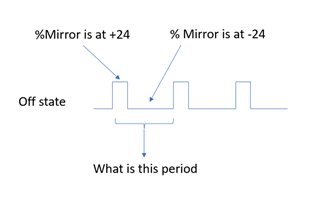
2- does DMD dithers in Off and Flat sate as well.
3- what is dithering range in angle in On-State, Off-Sate , and Flat state?
4- what is the dithering speed (frequency) in On-State, Off-Sate , and Flat state.
Background info:
We have a camera in system that at low exposure time, it starts to capture DMD dithering in off-state. We can see beating frequency between two system: By knowing above question we can do a better job in blocking scattered light in off state and change exposure frequency to get rid of beating frequency....
This is kindly urgent. Appreciate for quick response. Please point me to data sheet or any other document if I missed it.
Thank you
Babak