This thread has been locked.

If you have a related question, please click the "Ask a related question" button in the top right corner. The newly created question will be automatically linked to this question.

DLP3030-Q1: DLP3030 PGU LED board temperature reading

Part Number: DLP3030-Q1
Other Parts Discussed in Thread: TMS320F28023

Tool/software:

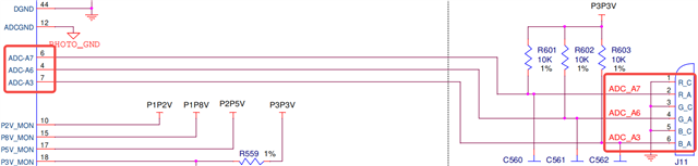
For DLP3030 PGU products, the temperature detection (NTC) of R/G/B three LED board are all connected to TMS320F28023, as shown below:

We have a few questions, please help answer:

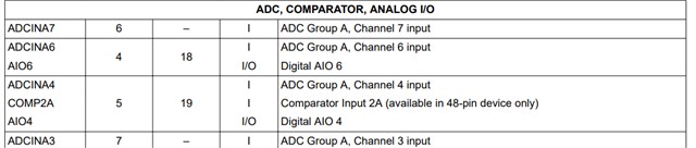
1. According to the specifications of TMS320F28023, these three pins are just ordinary GPIO, not ADC dedicated interfaces, so the actual detection software only sets the threshold of high temperature protection (turn off the backlight when exceeds a certain voltage value), instead of always being able to read the temperature value of the LED board,right?

2, R/G/B three LED board, can be arbitrarily connected to A7, A6 and A3?for example, not according to the TIDA080004 reference circuit diagram connection, such as blue LED board to A7, red LED board to A3, so the connection will be any problem?

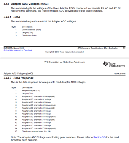
3, we use other MCU communication with TMS320F28023, can read the RGB three LED board NTC temperature value(through SPI)?

  • Hello Bruce,

    Welcome back to the E2E forums and thank you for your interest in DLP Technology. We hope to assist you with your questions. 

    Please see the following responses.

    1. I see in the datasheet these are  ADC inputs and in the Piccolo embedded software are intialized through the ADC code.

    2. I believe this would be okay.

    3. Yes, you can use the following command from the SPI programmers guide. Please take note of referring to section 5.3 for the read format.

    Regards,

    Alex Chan

  • Hi Alex

    Thanks for your reply.  I have two more questions :
    1. Can the SPI command read the overcurrent or overvoltage status of the LED part;
    2. Is there any requirement for the length and shielding of the connecting cable of the photodiode, as it may be a weak signal;

  • Hello Bruce,

    Please see the following responses:

    1. I do not think there is any overcurrent or overvoltage, you simply can poll and read back the adapter ADC voltages. You can implement logic to define and specify out what is considered overvoltage status for your specific setup. 

    2. Our cables are about 8 inches in length and make sure the photodiode cable has a grounded shield and the wires are in the twisted pair configuration.

    Regards,

    Alex Chan